
Linux kernel (IIO) driver for the ADS1299 on SPI, tested on a Raspberry Pi 4 and STM32MP257F-DK
 stephan
Brazil
Hi all,
For my undergraduate thesis I wrote a Linux kernel driver for the TI ADS1299 (and the ADS1299-4 and ADS1299-6). It is meant for two kinds of boards: standalone ADS1299 front-ends with no controller of their own, and boards where a Linux-capable processor (an MPU, such as a Raspberry Pi) talks to the ADS1299 directly over SPI. It does not apply to boards that put a microcontroller (MCU) with its own firmware between the ADS1299 and the computer, such as the Cyton as shipped.
Repository: ads1299-linux on GitHub
It is an IIO driver, so the channels show up in sysfs and samples are read from /dev/iio:deviceX. It supports:
- all data rates (250 to 16000 SPS) and PGA gains, per channel;
- buffered acquisition driven by the DRDY interrupt, with timestamps;
- lead-off detection, reported as IIO events;
- the internal test signal, shorted inputs, SRB1/SRB2 and the bias drive;
- the temperature sensor and supply monitors;
- a self test at probe.
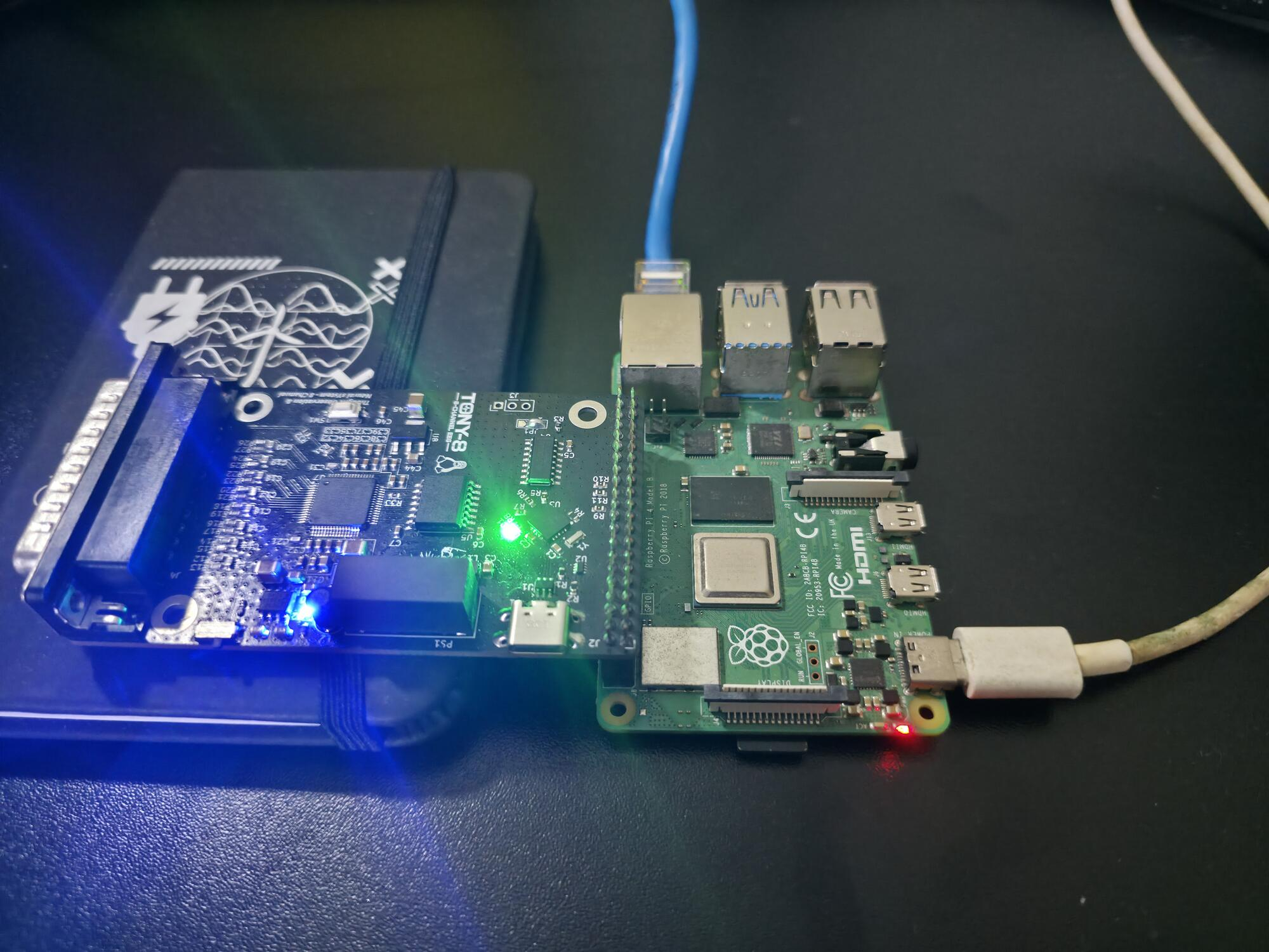
It comes with a devicetree overlay for the Raspberry Pi and builds out of tree (plain make or DKMS) on 6.6 and later; it has run on 6.6, 6.8 and 6.18.
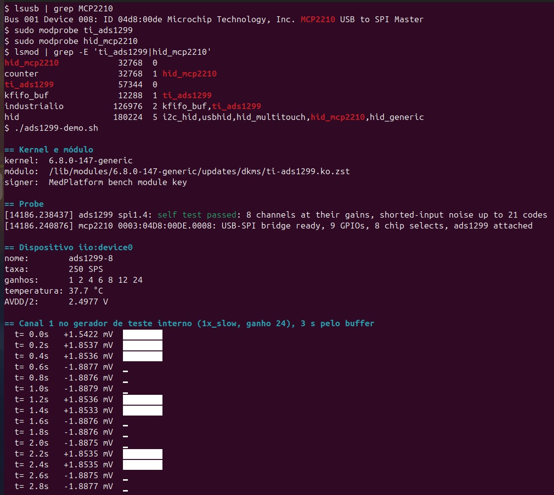
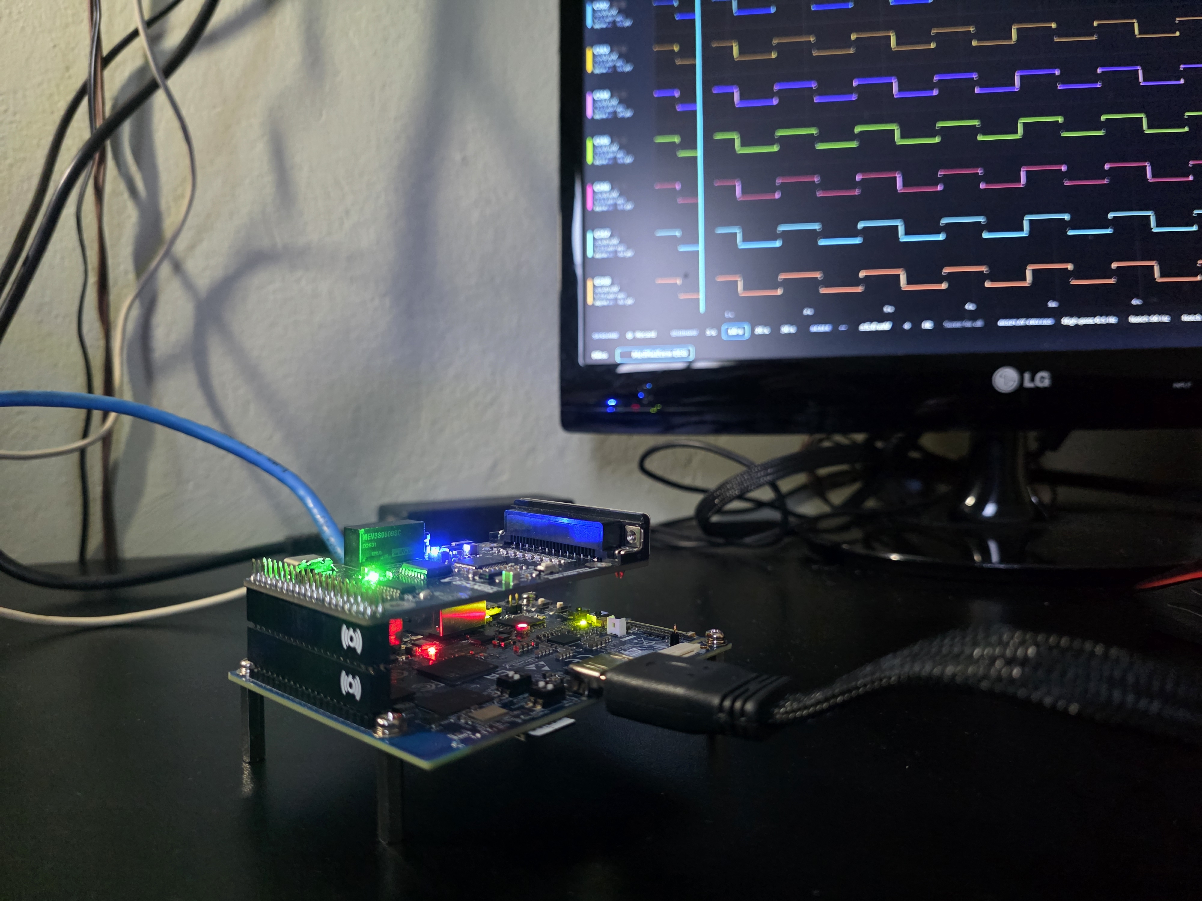
It also works without a devicetree and without a DRDY interrupt. On my own board, an STM32MP257F-DK running ST's Linux 6.6, and on an x86 PC, the ADS1299 sits behind an MCP2210 USB-to-SPI bridge: a HID driver for the bridge registers an SPI controller with the ADS1299 on it, and the driver reads each conversion on a host timer. On the PC that gave 10 s at 250 SPS with no lost samples; on the STM32MP2, with an earlier version of the driver, 30 min at 250 SPS lost 0.67 % of the samples on the USB link. The bridge driver is not published yet.
All features on one ADS1299 were tested on the Raspberry Pi 4 (Linux 6.18), the test signal on every channel within 0.5 % of the datasheet value, and lead-off events on open inputs, the bias drive, GPIOs, clock output and power down. Daisy-chain was not tested. The README lists exactly what was measured.
I've also submitted ADS1299 support to the mainline kernel. Following the review, it is being reworked as part of the existing ti-ads1298 driver, so the mainline interface will differ in some details from this out-of-tree driver.
Comments
Very impressive Stephan !
Here is a link to your LinkedIn post:
https://www.linkedin.com/feed/update/urn:li:activity:7517753340152213504/
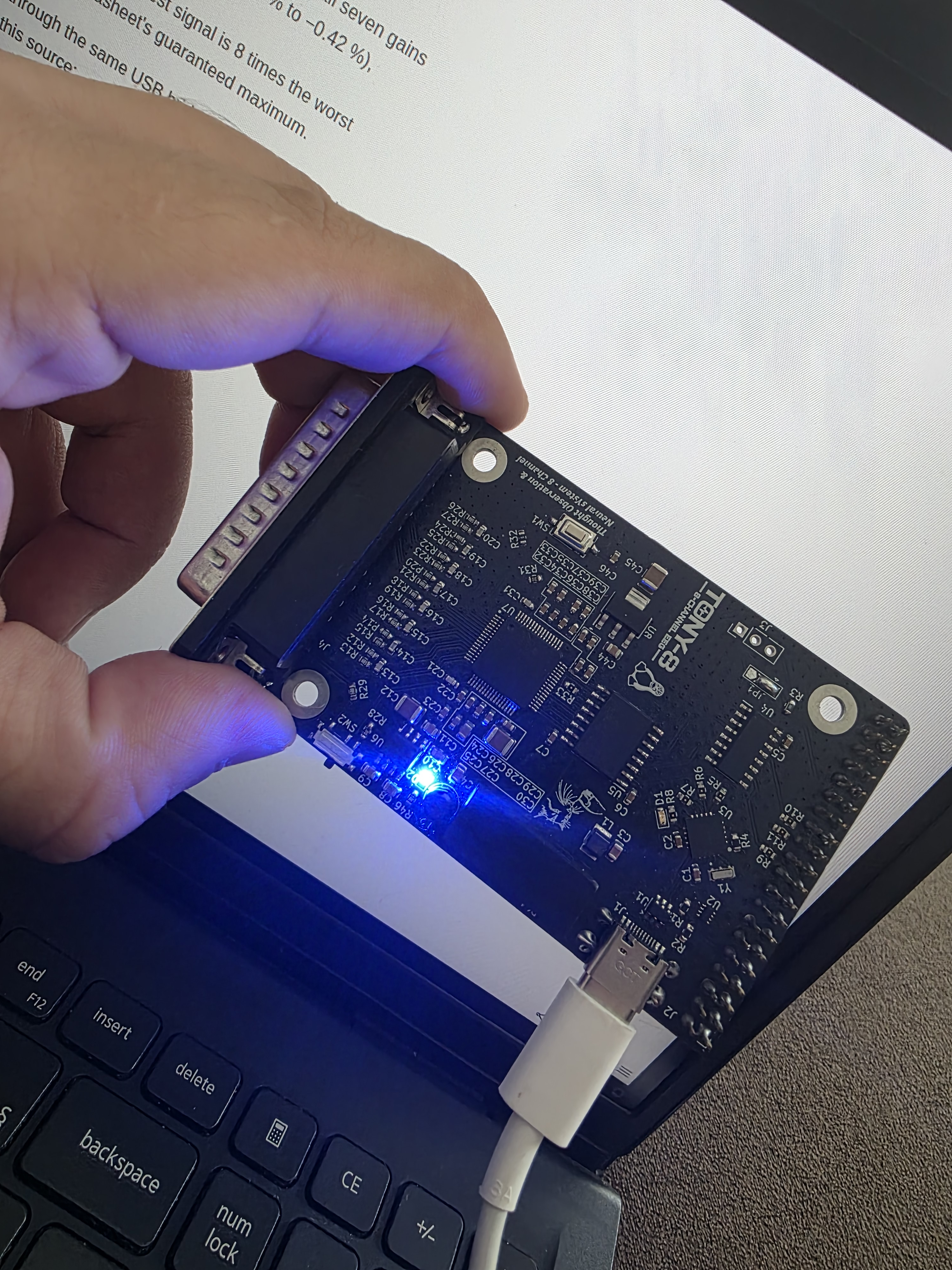
So the 'Tony-8' board is also your design? It's not mentioned on Github or LinkedIn.
What Raspberry software exists to talk to the driver? What applications are you envisioning?
Regards, William
Hi William,
Thanks! My work is based on a medical operating system built with the Yocto Project. I wanted an EEG as a proof of concept for it, so I designed one from scratch around the ADS1299.
Yes, Tony-8 is my design. The name is a small tribute to my cat, haha. I'm still validating the analog acquisition: delta, theta, alpha, beta, gamma detection, signal quality and the frequency spectrum. That's why I haven't published much about the board itself yet, but I'll release the full schematic and layout soon.
I went with a standalone board for the freedom it gives during development. It can be used over USB for bench tests, or talk SPI directly through the headers. It has galvanic isolation and protection against overcurrent, overvoltage and reverse polarity. I didn't go deep into the medical standards, though, so it wouldn't be a certified product, just an object of academic study.
As for userspace software, I haven't written anything beyond the generic framework of my OS yet. The driver uses the standard Linux IIO interface, so it's read through sysfs and the /dev/iio:deviceN buffer. On the Raspberry Pi my tests so far use a small Python script that reads it that way. I may port existing open-source tools so they can work with the driver.
Regards,
Stephan
Thanks. I wasn't aware of Yocto, here is their website for others to peruse:
https://www.yoctoproject.org/
Youtube intro:

Please post a note here on our Forum when you release.
I know nothing about IIO. So are you saying the framework / subsystem is flexible enough to work over USB as well as hardware port connections? That is impressive. So basically the same user level API in both cases?
A significant number of low cost BCI / EEG systems are not CE / FDA certified. And they state that plainly.
I'm sure you will consider adding a Brainflow 'device' interface:
https://brainflow.org/
https://brainflow.readthedocs.io/en/stable/
Regards,
Does the saved recording retain timestamp gaps when USB samples are lost, or is loss only reported as a total? Keeping those gaps visible would help avoid treating separated samples as continuous EEG.
Thanks William, and thanks for the Yocto links. I will post here when the board files are out.
On the API: yes, it is the same. The USB bridge driver registers (the MCP2210 in that case) as an ordinary SPI controller, so the same ADS1299 driver binds to it and the converter shows up as the same IIO device, with the same sysfs attributes and the same /dev/iio:deviceN buffer, whether it sits on the Pi's SPI pins or behind USB. A program does not need to know which.
What changes is behind the API. USB HID cannot deliver an interrupt, so over USB there is no DRDY: the driver reads each conversion on a host timer, and the timestamps are taken on the host. The driver says so in its timestamp_source attribute ("drdy_irq" or "host_timer"). The bridge also limits the rate: each sample needs at least two command and response exchanges, and each waits for the 1 ms USB frame, so the MCP2210 tops out at about 250 samples per second, the converter's lowest rate, however fast its SPI clock. Going faster over USB takes a different design
I will definitely build on this, an excellent suggestion. thank you very much
The honest answer today is: the total, not the gaps.
Each sample carries a timestamp, and the driver counts the conversions it never collected in lost_samples, reset each time the buffer is enabled. But over the USB bridge the timestamps do not show the losses reliably. After a late read the driver starts the next one at once, so the sample that catches up arrives with a normal-looking interval. In a 30-minute session at 250 SPS over USB there were 125 lost samples but only 49 gaps visible in the timestamps, the largest 9 ms. lost_samples was exact over the whole session, the timestamps were not.
With DRDY on the Pi's SPI pins it is a different case: 10 s at 250 SPS delivered all 2497 conversions that were due, none lost.
So I agree with your point. A total per session is not enough for that. What would fit better is marking the loss in the stream itself, for example a per-sample count of conversions lost just before it, so that a reader can see exactly where the break is