
Identical FFT and Time-Series Signals Across Channels on Cyton + Ultracortex Mark III

Hello OpenBCI community,
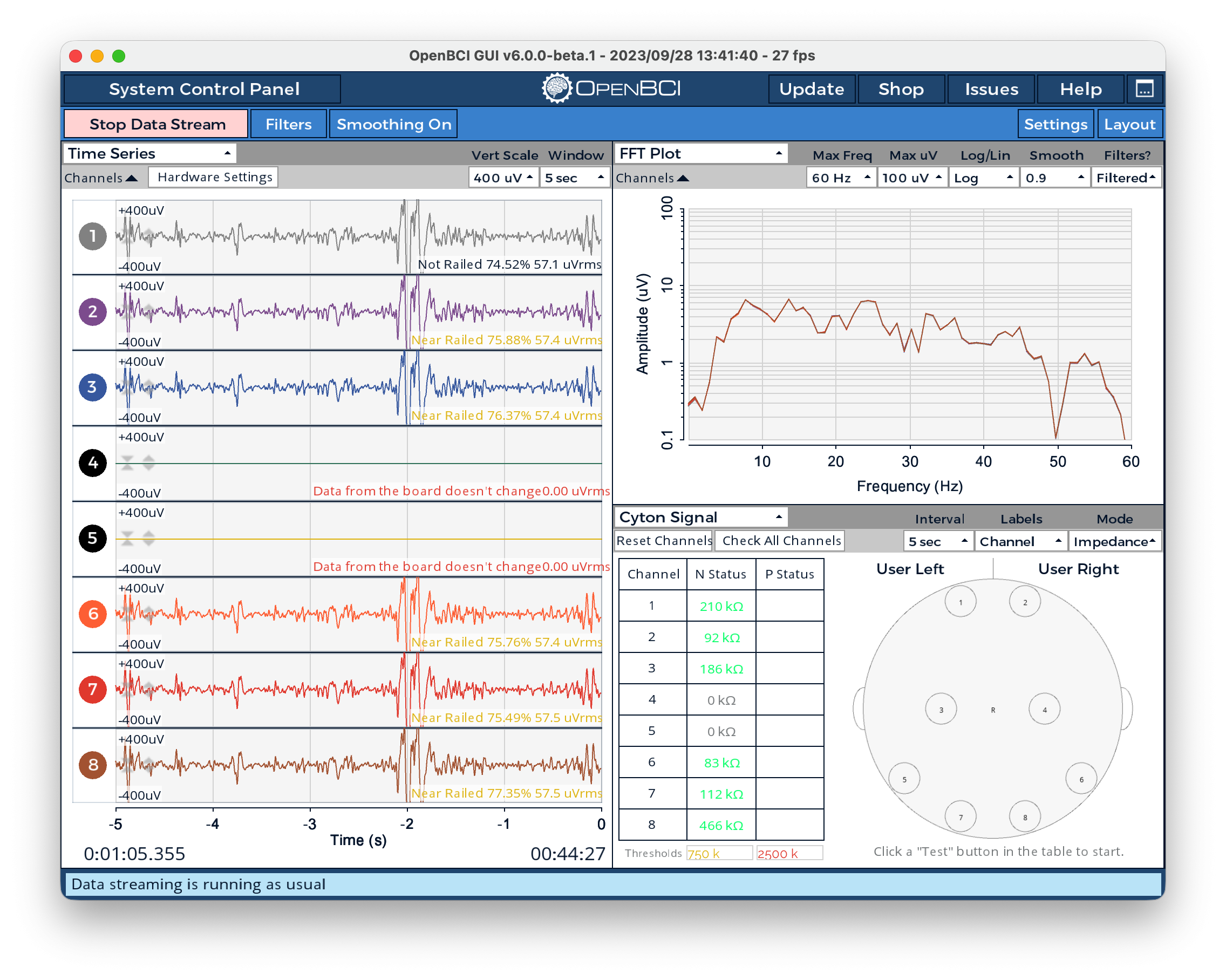
I would like to ask for help troubleshooting my Cyton setup. I have been wondering about this problem for a long time: why do the FFT plot and time-series signals from my EEG channels look almost identical across channels?
Current Setup
I am using:
- OpenBCI Cyton Board
- Ultracortex Mark III headwear
- OpenBCI GUI
- New electrodes and ear clip from Florida Research Instruments
I recently purchased new electrodes and a new ear clip from Florida Research Instruments to replace the old accessories, which were around 10 years old. I replaced six electrodes with the new ones.
Electrode Placement
My current electrode setup is:
- N1P: Oz
- N2P: O1
- N3P: O2
- N4P: Not connected
- N5P: Not connected
- N6P: Pz
- N7P: P7
- N8P: P8
In the OpenBCI GUI, I deactivated N4P and N5P because they are not connected.
Main Problem
When I look at the OpenBCI GUI, the time-series signals and the FFT plots seem almost identical across the active channels.
This makes me unsure whether I am recording real EEG activity from each electrode position, or whether there is a problem in the hardware, reference/ground connection, ear clip, or Cyton board itself.
Ear Clip Check
I read in some other forum posts that similar problems can be related to an ear clip or reference/ground issue.
However, I recently bought a new ear clip, so I am not sure if the ear clip is still the source of the problem. I also measured it using a digital multimeter, and the resistance was around 0.2 ohm, so the continuity seems good.
My Questions
If the FFT and time-series signals look almost identical across channels, what is the most likely cause?
Any guidance for troubleshooting this would be very helpful.
Thank you very much.

Comments
Hi @nugroho_budi
This looks like a reference / ear-clip problem, not the individual electrodes or the Cyton board.
The giveaway is in your screenshots: all active channels sit at ~57 uVrms and go "Near Railed" together, while the impedance check shows finite values (83–466 kOhm) — so the inputs aren't floating. That means every channel is dominated by the same common signal (mains hum + reference noise), which is exactly what a bad common reference does. On the Ultracortex all channels are Electrode_n − SRB2, and SRB2 comes from the ear clip. If that contact is poor, the shared term shows up identically on every channel.
About the 0.2 Ohm reading: that only proves cable continuity, not the skin–electrode impedance at the earlobe. The clip can be fine electrically and still make poor skin contact.
Quick things to try:
• Clean the earlobe with alcohol, add a bit of saline/gel, reseat the clip firmly.
• Confirm both SRB and BIAS are connected (separate pins on the board).
• Run the internal square-wave test — if channels then look clean and independent, the board/ADS1299 is fine and it's confirmed to be the reference side.
• Wiggle one scalp electrode: if all channels move together reference problem confirmed.
• Check the quality of your electrodes (even if new)
Hope this helps!
Hi, Dany. Thank you so much for your guidance. Oh I just know that there is an internal square wave test. I will try it.
So to confirm SRB and BIAS are connected, I will test it using multimeter.
Thanks.
@danysab,
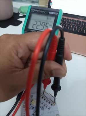
Hi, I measured the SRB pin and BIAS pin using DMM, is it correct that it has a value of around 4 MOhm, sometimes 20MOhm?
Hi,
That reading doesn't really tell you what you want, and 4–20 MOhm between SRB and BIAS is expected — don't worry about it. SRB and BIAS are separate nets and aren't supposed to be connected to each other, so probing across them on an unpowered board just measures high-impedance nodes through the on-board circuitry, which reads high and drifts. It doesn't confirm the reference is working.
What you actually want to check is continuity of each cable to its pin: put one probe on the metal contact of the ear clip and the other on the SRB pin — that should read close to 0 Ohm. That confirms the clip is wired through to the board. (Same idea for BIAS to its electrode, if you want.)
But the DMM can't measure the part that usually causes this — the skin–electrode contact at the earlobe. For that, use the GUI's built-in impedance check (it drives a known current) and the square-wave test. Those two will actually tell you whether the reference path is good in operation.
Ah, that's make more sense. Thanks, @danysab.
I will try it
A strange thing happened: instead of getting a square wave, I got an ECG-like waveform.
I followed the tutorial on https://docs.openbci.com/Cyton/CytonSDK/
When I send
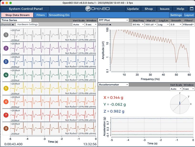
-,=,[, or], I get an ECG waveform with different frequencies and amplitudes.Did you turn off all filters?
The test signal really is a square wave, but the GUI applies a band-pass and notch filter by default, which reshapes it: the flat tops droop and the edges round off, so it ends up looking ECG-ish. To see it properly, do what the SDK docs say: turn all filters off and set the vertical scale to “Auto”. The scale matters too — the test signal is almost 2 mV, so with a fixed scale it gets clipped and distorted, which adds to the ECG look.
Let me know
Wow, great advice! works like a charm. Thank you
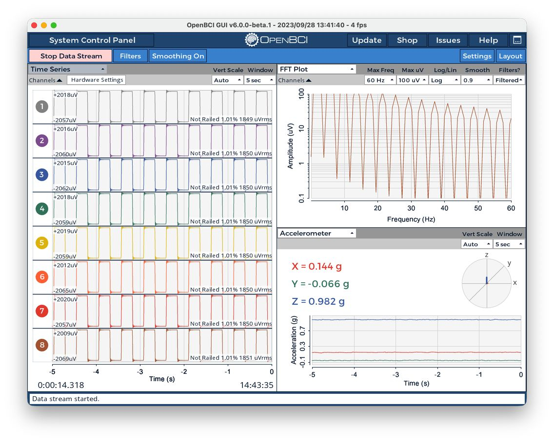
So, I think there is nothing wrong with the board.
After all of these tests, is it safe to say the cause of the problem is the ear clip?
That looks great! The board is fine.
About the ear clip.. could you post a picture of it? And don’t forget to clean your earlobe with alcohol before clipping it. Also you can try with saline gel if you happen to have some.
Okay, Thank you for the guidance.