high impedence

Cap preparation procedure:
- Subject hair/scalp is cleaned beforehand.
- EEG cap is placed on the head.
- Through each electrode opening, we use the syringe tip/needle carefully to move hair aside right beneath the hole that we see.
- Conductive gel is then inserted through the opening into the electrode cavity until contact is made with the scalp (we ask the subject as of now if he feels the gel if he says yes we assume that the contact is made).
- This is repeated for C3, Cz, C4, REF, and GND electrodes.
Now on the hardware settings button of the Open BCI GUI :
- SRB1 = ON
- SRB2 = OFF
- Bias = ON
- Input type = Normal
- Gain = 1x (i checked online and it is suggested to be 24x but i am not sure about it)
Reference/Ground placement:
Currently the cap’s built-in REF and GND positions are being used and they are on the scalp itself . We have not yet moved REF to the ear lobe or BIAS/GND to the forehead.
Current observations:
- We can clearly observe large jaw clench artifacts, especially on C3 and C4.
- Cz shows comparatively lower jaw artifact amplitude which i think is normal.
- However, eye blink and eye movement artifacts are not very clearly visible because it might be covered due to noise.
- In the OpenBCI GUI impedance/N-status check, we typically see around ~5000 kΩ impedance per channel even after all the gel application.
Our current analysis/suspicion:
We suspect the issue may be related to one or more of the following:
REF/GND placement,
using the top pins instead of bottom pins,
very high impedance,
i think if the impedence can be brought down to an acceptable level the noise would itself reduce and we will be able to see the signals like eye blink and eye movements
Comments
Hi GG,
You mention that you changed the SRB1 / SRB2 settings. Don't do that. Use the default which is SRB2. Also use the default pins, which are the 'bottom' pins closest to the board surface. Use the suggestions on the tutorial:
https://docs.openbci.com/GettingStarted/Boards/CytonGS/
https://docs.openbci.com/GettingStarted/Biosensing-Setups/EEGSetup/
https://docs.openbci.com/AddOns/Headwear/ElectrodeCap/
William
HI William,
Thank you for your advice. We tried it, and it reduced our impedance to below 100 kohms.
When we connected to all the bottom channel only for the cyton we were getting the channel railed for some reason that is why we didn't consider it previously now that the impedance is ranging from 60 - 120 kohms on the channels being used (significantly less than the 5000kohm that we were getting previously ) we want to get it below the accepted threshold of 20 kohm as suggested in multiple literature that it is good enough, so can you please suggest as the ways we can get this 120 kohms to below 20 kohms. We also have a complete apparatus video that we can provide if that helps please do let us know.
Please read this comment regarding acceptable Cyton impedance ranges,
https://openbci.com/forum/index.php?p=/discussion/comment/13328/#Comment_13328
Your '20K ohm' figure is obsolete, given that the Cyton (ADS1299) amplifier input impedance is ONE GIGAOHM.
Thank you William , you're the goat")
We are using an OpenBCI Cyton and are trying to connect all 8 EEG channels. We start connecting from the SRB pin and place the electrode leads on the row of pins closest to the board.
Due to the limited physical space between the pins, we are unable to fit all 8 channel connectors on that row. By the time we connect Channel 7, there is not enough room left to connect Channel 8.
In this situation, would it be okay to connect Channels 1–7 on the bottom row and connect the last channel (Channel 8) to the corresponding pin on the top row instead? Has anyone done this before, and would it work correctly?
No. You are misunderstanding what SRB2 does. It 'gangs' together all the upper row pins to become the common reference electrode.
I don't know what header pin female connectors you are using, but they sound too large or malformed. Here is an example of header pin jumpers that are the correct size.
https://www.adafruit.com/category/306
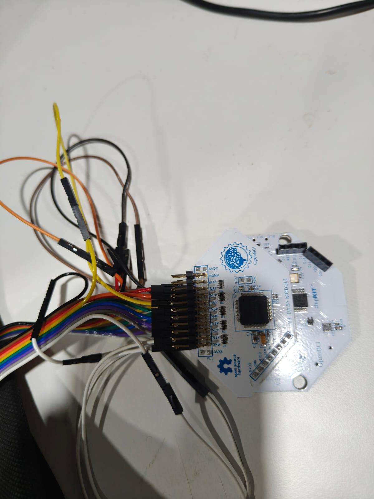
We actually meant that we are using the official openBCI apparatus only, but as you can see from the image, once all of the pins are connected except one, there is not enough space left for the last pin. In this case, as shown in the image, the yellow pin isn't fitting in the bottom like others, so can we just fit that yellow pin on the location right above it in the same channel
Your photo is from March? Please describe in text what you found to work. Your header connectors appear to be the right width in that photo. So all channels should connect
This picture was clicked yesterday only as we are in India it follows DD/MM/YYYY format
Did you find a solution?
yes, we did because the jumper cable have excessive width we got some male to female jumper cables from our robotics lab and connected to that our cyton then the male side to the female side of the openbci cables this helped as connect all the channel it does make the apparatus messy although the signal and impedance is good