
Root cause no data streaming for Cyton
 atjohnso
Boston, MA
atjohnso
Boston, MA
Hello,
I'm part of a senior design undergraduate engineering team attempting to use the Cyton board in an EEG project. We've built the board ourselves following a method similar to @alwayswearshats' procedure described here, albeit using a wired USB connection instead of the WiFi Shield. We're able to detect the Cyton board in the GUI and start a session, but receive a data streaming error after clicking the "Start Data Stream" button. We were able to successfully install firmware to the board from Arduino IDE and verified sending and consuming I/O between the board and computer. In rudimentary testing we know board.streaming is always false and so is board.channelDataAvailable. I have two main questions:
- How might we root cause the problem?
- Can any methods in the library be used to test if our sampling chip is dead?
I've included screenshots from the OpenBCI GUI below and attached the output from the console.
Thanks!


Comments
I can assess the console log. There are no BrainFlow errors, so the Dongle is able to send commands using BrainFlow. We don't get a full call/response from the Cyton board with BrainFlow commands, only that the Dongle has sent them. The board however does not start streaming.
There also seems to be errors with OpenGL and this computer, though it doesn't seem to crash the GUI. OpenGL is required by Processing to render the application
Thanks for your response @retiutut. We're able to start data streaming by sending a
'b'command through the serial monitor in Arduino IDE, but we're still not getting any sampling data. The indication from the board is there is no new channel data available. We used a digital multimeter to read the DRDY bus between the ADS sampling chip and PIC32 microcontroller and found that DRDY is always high, implying that there's no data. Any idea what may be causing this?After digging into the data sheet for the ADS1299, we've located the issue. Our design utilizes a Texas Instruments ADS1296 in place of the ADS1299 for sampling EEG data. When comparing the data sheets of the two ADCs, we noticed a difference in capacitance between VCAP1 and AVSS as well as the presence of a capacitor between WCT and AVSS as seen below:
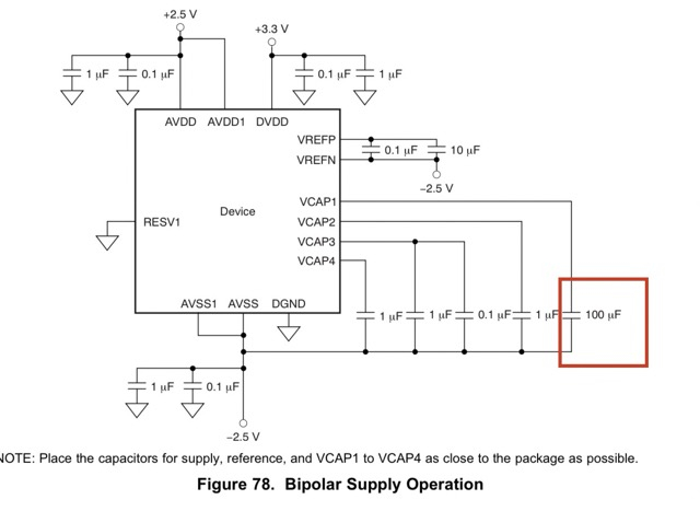
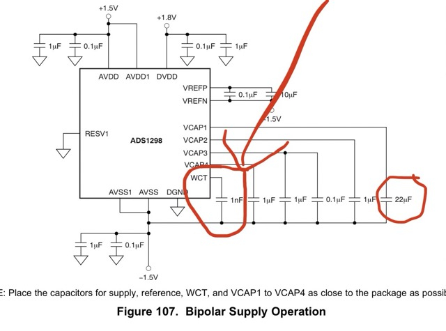
After rectifying these differences, our ADS sampling chip now functions properly. It appears the difference in power up configuration between the two product lines was our problem. While we are able to stream data now, we're still unable to do so from the GUI. In the firmware, we noticed that the board can send the ADS ID by reading the ADC's register 0 value. We also saw that it checks for the presence of a Daisy module from register 0, and ensures it matches the ADS1299 ID from the data sheet exactly. Is there a place in the source code of the GUI where it does any similar checks?