
Strange signal from one of my daisy boards.

Hi All,
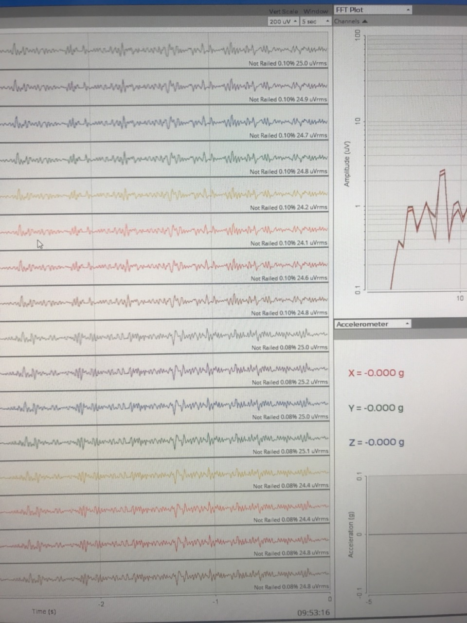
For testing whether a daisy board is working, I compared signals obtained from a CYTON in combination with 8 daisy boards under a condition in which I short the two SRB pins, the CYTON's BIAS, and the 16 low NP pins. Seven daisy boards yield flat signals (Not Railed 0.01% 0.10 uVrms), but one shows spike from time to time, cf. the attachment. I am not sure if this is an expected behavior because I cannot get "clean" signals even the setting is ideal. I would be glad if someone could give a comment about this. Thank in advance 
Best, Attha
Comments
Please send an email to contact at openbci.com (customer service), and ask how you can proceed. I assume this is a recent purchase?
William
I sent the email to [email protected] for a week but have gotten no response yet. Maybe, I sent the email to the wrong address. Could you please inform me the correct email address? Thanks in advance.
There are several OpenBCI mailing addresses. I believe 'sales' may go to staff that work with larger institutional purchases. I originally recommended 'contact' above, as I know that reaches customer support. It's possible some staff are out of the office last week or this week due to the US Labor Day holiday weekend and "end of summer" activities. Suggest trying contact again, either for the first time, or followup. It should put you into the 'ZenDesk' automated customer response system, where they track incoming questions.
I don't actually see any 'spike' in the photo you posted above. But you somehow have wired all channels to the same scalp location?? If you indeed wire connect channel(s), reference, and Bias together, it should produce close to zero microvolts. If you are not seeing that I would suspect your cabling first, before assuming all 16 channels (TWO ADS1299 ADC chips), are producing anomalies.
Signals of the "good" boards that I think produce expected signals are shown below
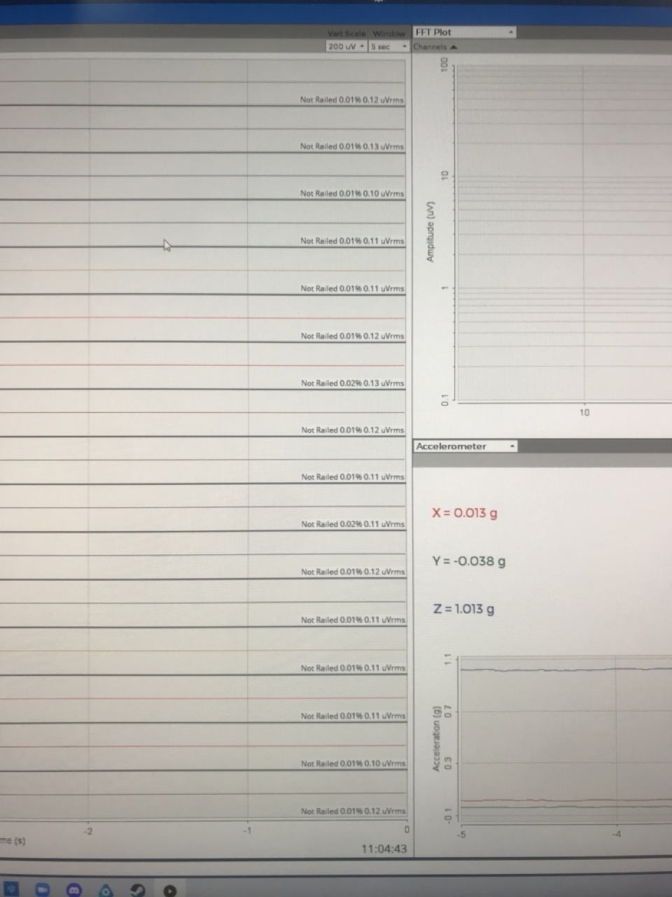
When I replaced the daisy from the "good" boards on the "bad" board, the produced signals are what I expect.
For the cython alone, the produced signals from both "good" and "bad" boards are what I expect. Or do you mean something else when you mentioned "Only ONE reference pin is used, SRB2, the lower pin. Not both SRB2 and SRB1 (the upper pin)."?
ONLY use the LOWER reference pin, SRB2, on each board. The first image you show does not depict 'spikes'. It is just the same scalp location EEG on all channels.
I also am now noticing that your first image shows identical scalp EEG on channels 1 to 8, but a slightly different (all identical) EEG on channels 9 to 16. This must be because of something about your wiring, no?
I followed the instruction of connecting daisy and cyton given in https://docs.openbci.com/GettingStarted/Boards/DaisyGS/ . Do you mean I should not use SRB1 in daisy+cyton?
There are TWO 'SRB' pins on each of the Cyton mainboard and Daisy. The lower, bottom, closer to board SRB is SRB2. That is the one used for EEG reference. The SRB1 pin, farthest from board surface, is generally NOT used. The Y-cable mentioned in your link, is connecting to the SRB2 pins on both Cyton mainboard and Daisy, closest to each board.
https://docs.openbci.com/GettingStarted/Boards/DaisyGS/#2-connect-y-splitter-cable