
Flashing Cyton with DefaultBoard "Program flash failed"

We have an electrode cap kit, and are having issues flashing an arduino sketch onto the Cyton board. We were able to successfully flash the Cyton board with the DefaultBoard example one time, but after making some changes to the DefaultBoard to add a button push event, we failed to flash the Cyton board. Now, all of our Arduino sketches seem to fail to flash. The error that comes up everytime we try to flash the board looks like this.

As of right now, the Cyton board LED doesn't turn on when the board is powered on, but the LED does flash when the board is put into boot loader mode.The BLE dongle does light up blue when plugged in, and while trying to upload the sketch, the dongle flashes a red light and a green light, but the sketch always fails with the above error message. If you could provide some guidance on how to troubleshoot this problem we would greatly appreciate it.
Comments
Check out the suggestions in the Troubleshooting section here:
https://docs.openbci.com/docs/02Cyton/CytonProgram#troubleshooting
Some related threads, found with the Google Advanced Search button in right column:
https://www.google.com/search?as_q=cyton+program+flash+failed&as_sitesearch=openbci.com
Can you mention why you are desiring to replace the default firmware? You state:
Button press events can already be recorded using the External Trigger feature:
https://docs.openbci.com/docs/02Cyton/CytonExternal
Finally, the two RFduino radio chips (dongle and mainboard), are independent of the PIC32 firmware. Thus radio channel status and changes can be made from the GUI directly. Confirmation of this functionality would verify that your radios are healthy.
https://docs.openbci.com/docs/01GettingStarted/01-Boards/CytonGS#5-optional-settings
Expand Section 5 with the arrow.
Regards, William
I am working with Dr. Gage and BYB on this issue, and I can explain why we are trying to make changes to the DefaultBoard. Although there is documentation on how to use the native External Triggers, I have not been able to find documentation on where these external triggers get saved and how. We were hoping to alter the DefaultBoard code so we can add a button through one of the extra pins (D12 to D17).
As far as troubleshooting goes, I have tried closing all tabs, restarting my computer and attempting to flash the board again, but I ran into the same error as before (Original Post). I am using an Alien Ware Razer computer with the following specs, so I don't think my computer is too slow: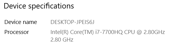 .
.
I am now trying to check the RFduino to see if it is communicating properly, but I am having a hard time doing so, because the board connects to the GUI, but doesn't show any data.
The Cyton data stream contains 8 EEG channels and 3 'Aux' channels. Normally the Aux contain the accelerometer, but they can be switched (with the GUI or serial port SDK commands), to instead capture 3 pins on the PIC32 header. In either analog (0V to 3.3V) or digital mode. There is no need to modify the firmware. I previously gave you the link with the documentation. DId you take a look??
https://docs.openbci.com/docs/02Cyton/CytonExternal
https://docs.openbci.com/docs/02Cyton/CytonDataFormat [data format, also saved in recordings]
I previously suggested testing the RFduino's separately from actually starting the data stream. I gave instructions on how to do that.
So you use the menu in that section to try to get the radio channel, change the channel, autoscan, etc.
As you can see from the image above I was able to show that the RFduino is in fact connecting.
I also noticed that when I have been turning the Cyton board on I have consistently been setting it to BLE mode. I tried flashing the board while it is in PC mode, and it failed as well, but I still get the same error in the arduino IDE as the original post > @gagegreg said:
I don't think I understood before how to change what data gets put in the 'Aux' channels, because I did not see this option in the GUI. I looked at the link (https://docs.openbci.com/docs/02Cyton/CytonDataFormat) that you mentioned to see how to alter the Aux data that gets written to the output file, but I do not see any instruction on this page for how to change the Aux data type in the GUI. Could you offer some guidance on how to set the first Aux channel to log events?
When I suggested you test your RFduino's (dongle and mainboard), I was referring to the buttons: Get Channel, Change Channel, or Autoscan. These actually exercise the channel setting functionality of the RFduino's.
There is no difference in the position of the switch BLE and PC both just mean 'on'.
Did you look at the suggestions at the link I gave previously?
https://docs.openbci.com/docs/02Cyton/CytonProgram#troubleshooting
Regarding:
The GUI has a widget for changing the Aux data to analog or digital mode.
https://docs.openbci.com/docs/02Cyton/CytonExternal#using-the-openbci-gui
All the above 'docs' links are now somewhat obsolete after the upgrade today (July 27th) of the 'Docusaurus' package used to maintain 'docs' section of the website. Here is an example of the old link style and the new format:
https://docs.openbci.com/docs/02Cyton/CytonExternal#using-the-openbci-gui [old]
https://docs.openbci.com/Cyton/CytonExternal#using-the-openbci-gui [new]
Basically numbers and dashes disappear, and the '/docs/' internal folder element is eliminated.