
Correct Cyton cables setup for 5-lead ECG?

Hi,
Asking a question as did not find this in previous threads.
I am setting up Cyton for ECG using 5-lead concept using the doc guide how to connect which electrode to which pin and which position (https://docs.openbci.com/docs/01GettingStarted/02-Biosensing-Setups/ECGSetup).
1. In the chest picture there, 5 electrodes are shown, but text tells the 7 are used. Picture also has LA location listed twice?
2. The scheme of leads below that only has 6 electrodes for 3 locations, LA,LL and RA, and others are not shown, is this so? I understood it in the way RL goes to AGND and V goes to 4P and SRB, correct?
3. Finally I seems confused with pins connections, as in one post it was written that 3 Y-cables are needed for connection and "you have to make them"? This would explain lead connections, as otherwise there would be 9 electrode connectors but only 7 electrodes. However, the doc does not mention any Y cables...
Anyone could explain or maybe post a picture of the correct setup?
Thank you for help!
Michael
Comments
Hi Seqvera, This is the original thread on 5-lead,
https://openbci.com/forum/index.php?p=/discussion/2098/5-lead-ecg
The current docs / ECG Setup page is INCORRECT in recommending AGND. You should use the Bias lead instead. Mentioning Eva @evaesteban. AGND is only for internal usage, such as active electrodes. See recent thread here,
https://openbci.com/forum/index.php?p=/discussion/2687/eeg-cap-kit-noise-issue-eeg-emg-eog-agnd-resolved
AGND could work if no EEG is involved. Otherwise you will get noise because AGND is a low impedance connection. My suggestion is to repair all the AGND references in docs, if there are other pages.
William
The diagram in the original thread is very clear. The diagram in the new doc, considerably less so. Even though I recommended incorporating the diagram from the original thread. @evaesteban, @retiutut.
Thank you!
So if I got things right, there is the following connection of electrodes: LA -> 1P, LL-> 2P, RA -> 1N, RL -> BIAS (not AGND), V -> 4P (see also below for V electrode)
1. The scheme in the ECG Cyton guide says: "For example, IN1P LA means you connect top N1P pin on the Cyton to the Left Arm location shown on chest diagram above. Do you see the (diagonal) line connecting IN1P LA to IN3N LA? That means you'll be measuring the potential difference between IN1P LA to IN3N LA. IN3N LA means you connect bottom N3P pin to Left Arm location."
Should this be understood that 1P and 3N needed to be connected together? And also 1N to 2N (RA) and 2P to 3P (LL)?
Does this do something with Y cables, or how it supposed to be connected? Or there are TWO(?) LA electrodes (which I do not think so)? Or does this one scheme actually talk about "Leads" and not cables...
2. I am still confused with mentioned first SEVEN and than SIX sticky electrodes, as the scheme only shows 5 of them. And later the guide says: "If you want to sample electrode V, it will require two additional electrodes, one plugged into the N4P bottom pin of the Cyton (corresponding to Channel 4) and the other one plugged into the bottom pin SRB2" so where this 2nd V electrode (i.e. 6th or 7th?) should be placed?
Thank you for suggestions!
Michael
Please follow the directions in the thread, not the docs page, until the docs page is corrected.
https://openbci.com/forum/index.php?p=/discussion/2098/5-lead-ecg
Made an issue linking to this thread on Github and sharing with OpenBCI team. https://github.com/OpenBCI/Documentation/issues/33
Thank you William,
Now I was trying to gather a guide from those 2 threads you mentioned:
Is this what it should be?
After doing this, GUI, dongle, Cyton made connection ok, but I did not see ECG signal and rather some EEG-type noise:
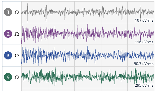
so I guess something is not right...
Did I miss something in the setup? Thank you again!
Michael
It looks like you may not have the mains frequency notch filter turned on. A bandpass filter is also useful.
Are you sure you understand the usage of the 'V' lead? Leads I, II, III, are all bipolar, and do not use separate 'reference' / SRB connection. But 'V' is unipolar according to the diagram, so will need to be referenced to another point. Or possibly actual medical EEG equipment does some kind of "averaged reference" based on the RA, LA, LL points. You'll have to research this. The other thread has some links to ECG docs, for example discussing the derived 'Leads'. Which use average computations.
The Bias on/off settings in the Cyton settings panel control the mains out-of-phase current injection. This only applies to EEG. Is not strong enough for ECG. Bias in settings should be off on all your ECG channels. SRB1&2 also all off for ECG.
William
Hi William
Thank you again. Yes, I have 50 Hz notch on and bandpass filter 1-50 Hz (tried others as well). Need maybe to check if the connectors and electrodes are firmly attached.
And I catch V electrode logic (also Wikipedia link you sent is very clear on computations); my problem was to follow threads and guides step-by-step, which have some different texts as mentioned above. Should I try attach this V-electrode another wire via Y-connection to SRB2 (as shown in some texts)? But would it make much sense as SRB1/2 are all off? Which ref.point would be best (as it is unipolar and as 4P, I guess the wire should be in some special connector?). Or course I may try also without V to see if all works.
Tomorrow will try check connections, and with all BIAS=OFF. Maybe need to do some research on V use...
Michael
Are you sure you need 'V'? I get the impression it is not widely used.
SRB2 is a common reference bus that by default, connects all the IN1P, IN2P, ..., IN8P pins together and presents as the SRB2 pin. This bus is primarily used for EEG.
How long are your ECG leads? The other thread recommends as short as is reasonable, say 5 feet or less. Long leads will pickup noise from AC noise generators in the environment: ceiling, wall, floor wiring conduits, extension cords, wall warts, power supplies, LED lighting, etc.
If you DO need V, it will require a separate reference. Do NOT connect to any of the channel 1, 2, 3 pins, as that would distort their readings (summing the V location voltage).
Can you explain your application for multi-lead ECG? What is your goal?
OK, clarification on the V lead. If point V is connected IN4P, then IN4N can connect to any of the other existing skin electrodes, or a new one that you place. You stated above:
Which kind of implied you were considering connecting skin-point V / IN4P to some other existing point / channel pin. That would indeed distort the other Lead with the potential at skin-point V. But using IN4N connecting to an existing electrode is ok.
Hi William,
Thanks, this might be case.
Also, as I am using Mac, I found this noise could be an issue with missing/improper FTDI driver (.kext). Will check that too (found a doc page about that).
And as in previous:
No, but I try to experiment with V and without V to see which differences it may give. It might be interesting to see the effect of relocating it from V1 to V6 whereas others will be the same. As shown earlier, they should be able to catch different vectors.
No, they are short, about 2'. Should be no problem.
First learning the ECG signals acquisition and later try to apply different HRV processing. We are interesting now e.g. to compare different open source algorithms vs. the same sources file. So basically the simplest setup which produces all the essential waves and allows a simple analysis for deviations.
Will let you know the progress.
Michael
re: 'simplest' HRV
I've used this app in the past with a simple Polar chest strap. Works great and is in use by a large number of athletes and trainers. Many HRV devices provide the IBI inter beat intervals (in milliseconds) directly via Bluetooth.
https://www.hrv4training.com/
https://www.marcoaltini.com/research--publications.html
I really doubt that you need 5-lead ECG to get accurate HRV analysis. My impression is that 5-lead and 12-lead ECG are for cardiologists wanting insights into detailed heart rhythms / muscle / valve firing. Certainly the setup time is huge and unwieldy unless you are an MD / cardiologist.
Another innovative company is Valencell, which has HRV gear in several form factors: ear buds, arm bands, etc. They sell their chip to manufacturers. The chip does de-noising, and accurate IBI determination. Chest strap generally gives most precise IBIs, but these other devices (using PPG principles), can be equally accurate if noise and motion artifacts are removed.
https://valencell.com/
I honestly don't know what is causing the noise in your ECG signal. Have you tried the simplest possible setup as shown in the tutorials?
https://docs.openbci.com/docs/01GettingStarted/02-Biosensing-Setups/ECGSetup
This was the earlier version of the Cyton electrode tutorial
https://github.com/openbci-archive/Docs/blob/master/Tutorials/01-Cyton_Getting Started_Guide.md#4-launch-the-gui-and-adjust-your-channel-settings
That doc was doing simultaneous EEG, ECG, EMG, so adjusted the scale factor on ECG channels.
Regards, William
Hi William,
Thank you for suggestions.
Yes, and we have used also others simple like gHRV which is easier than e.g. Kubios. But I haven't previously gathered the data myself, only use some recordings.
Yes, as I said just got the idea that V location changes might be interesting to try.
Yes, I did with only 4 electrodes (RA, RL, LL, LA). The result is likely the same whatever I tried: SRB, Bias, notch filters, band filters... Indeed when 50Hz notch is off, this gives nearly a white noise, and when it is on (also for 60 Hz on), some patterning can be seen but nothing related to "normal" ECG.
GUI widgets of course react when electrodes are touched or moved, and there seem to be no problem with communication between the dongle and Cyton. I was suspected FDTI drivers, but this seems to be not the case. Also tried different USB ports on dongle, no differences.
Perhaps I will try in few days with another Windows system, may have 7 and 10. Could be that desktop Mac gives some interference I can't get rid off. And use 5.0.1 update....
regards,
Michael
Oh you meant only 3 electrode setup (IN1P, IN1N and BIAS instead of AGND)? Did not yet try...
And I did not touch gain, maybe need to set all to 8x indeed... could pick up extra noise otherwise.
Michael
Hi William, some extra attempts made:
1. Tested 3 Lead (IN1P, IN1N and BIAS) connection (gain 1x-8x, normal, not included bias, SRV2/SRB1 off/off) no effect
2. Changed to other cables and electrodes, no effect; trying connection to different pints, no effect.
3. Manipulating notch: when off indeed there is some (not much) 50Hz noise but no major changes. Band filters affect the signal chariness, but this is expected.
4. Powering all but one channel - no major changes. I wonder why FFT plot shows spectra when all those channels are off:
What do you mean by "no effect"?? You could not get 3 lead ECG to work? If that is the case there must be an equipment failure.
Yes, I meant no reasonable signal (no regular pattern as I could catch) from 3 leads. But I will try other Win10 computer first; may suspect Mac issues...
When did you purchase this Cyton? Has it ever worked correctly following the Cyton tutorials?
https://docs.openbci.com/docs/01GettingStarted/01-Boards/CytonGS
Bought about 3 weeks ago. Yes, did start with tutorial and these are examples with Cyton without any connections or cables:
It reacts of course as I touch electrodes (note "railed" and "not railed" appear somewhat random, when the session starts).
I wonder why it shows very high uV signal (gain set 24x default, is this normal at free pins)? Does this simply means battery power (i.e. 4-5V)?
As of windows: found the error claiming "Boardcontrol.dll cannot be found" (but the file is definitely there...). Running as admin does not change this.
Thanks!
Michael
Michael, hi.
Results with unconnected pins are not predictable, but generally produce very low microvolts. A better self-noise test is to connect 3 pins together: channel, reference, and Bias. This should produce very close to zero microvolts.
Touching pins will of course produce randomly high values.
Please go through all the steps of the tutorial, and see if your results are the same.
https://docs.openbci.com/docs/01GettingStarted/01-Boards/CytonGS
https://docs.openbci.com/docs/01GettingStarted/02-Biosensing-Setups/EEGSetup
https://docs.openbci.com/docs/01GettingStarted/02-Biosensing-Setups/ECGSetup
I believe you are saying that 3 lead ECG just produces noise. Correct? This should not happen and may indicate your board is defective. Try the EEG Setup as well.
William
Update to previous:
This is how 3 lead system looks with supposed to work setup. I noted that accelerometer shows up to +/- 0.7 g even Cyton board is laying on the table. Is this how it should be (I guess not)?
Thanks William, will try in couple of days. Did not use EEG before, will read.
Well, I can only see random signal in 3 lead ECG and it does not react on bias, gain etc., neither looks as it should be according to tutorial.
Michael
Please try the 3 pin self-noise test I mentioned.
What electrodes are you using for ECG?
Hi William,
1) tried 3-pin self- noise and it has worked on both Mac and Win10 (nearly zero noise), even with 50Hz pitch off so it can't be due to mains or nearby comp alone.
2) did not manage to start GUI on Win7 and Win Server 2008 R2 (likely java problem, as it cannot find BoardControl.dll, even java.library.path show it should be there). BTW, had the same message once or twice on Win10, but than GUI started normally.
3) tried EEG setup tutorial. Nothing like that was obtained (although uV signal seems reasonable, band power columns do not move, neither there is any reaction on eye blinking, moving, etc.; electrodes connection were with head band on channels 2 and 7: I tried 2 different cables):
4) to check if this is a dongle problem, I borrowed dongle from a friend and it has no difference. Also, he tried my dongle with his Ultracortex and it works perfectly. Hence I think there should be something with my Cyton (but not with computer OS)
5) I checked also analog input (D11) with pulse sensor; works perfectly.
Is there any simple way to test whether something in Cyton is somehow defective?
Michael
Michael, hi.
Your next step is to email contact at openbci.com and request customer service exchange of your defective Cyton mainboard. Thanks for the dongle test. I assume your friends Cyton + dongle works fine on your computer?
It's likely the ADS1299 analog to digital converter is defective on your board. The PIC32 D11 input is handled by the microcontroller on-chip converter, so bypasses the ADS1299.
GUI only works with Windows 10, is no longer supported on Win 7 or Win Server 2008. But your normal system is Windows 10.
William
Thank you William,
Yes, that other Cyton+Daisy with dongle works fine with EEG on both Win10 and Mac, only this new Cyton does not. I was trying on older GUI version on Win 7, but same outcome. In Win10 it also complains about missing *.dll files, but connects anyway.
Here is some update (without good output so far), before asking to change the Cyton:
etc. but then it connects and seems to work...
(I guess this is not too normal?)
Michael
Since you have already done the tutorial tests (EEG, ECG), which failed. It's clear you have a bad ADS1299. The fact that the Pulse Sensor works (using the ADC on the PIC microcontroller), further confirms the issue is with the ADS1299 and not the main microcontroller. Finally this is a new Cyton that has only failed consistently, never worked as expected. All of these are reason to contact the support email and ask about exchange.