
Capturing and analyzing a signal to identify patterns.
 masteroforest
Russia
masteroforest
Russia
Good afternoon!
We have an Electrode cap. Please indicate the normal working range of the channels. I know that the use of electrode gel is necessary. But I checked the hardware connection (without gel) and the resulting amplitudes on some channels reached 1000 uVrms.
I'm shallow still in the BCI topic. In accordance with the master's work, the task is to submit and recognize 2-4 cognitive inventions. Please tell me what is more applicable when working with OpenBCI: frequency or time domains are better to use, statistics or neural networks are better to use for analysis, and which commands should the operator use: mental or emotional?
Best regards,
Dmitriy
Comments
Dmitriy, hi.
Electrode caps MUST be used with gel (electrolyte). Without the electrolyte you are just picking up noise. Normal level EEG is generally below 100 microvolts. But EMG can contaminate it, pushing it into the millivolt range. A bandpass filter, say from .5 Hz to 45 Hz, will remove the EMG noise.
Here are some relevant search results / links:
https://www.google.com/search?as_q=affective+bci&as_sitesearch=openbci.com
https://www.google.com/search?as_q=motor+imagery&as_sitesearch=openbci.com
Good summary of various BCI paradigms,
https://www.gtec.at/product/bcisystem/
Regards, William
Thanks for the information provided.
In general, the task is to control the movement of the technical object. In real time, a mental (non-emotional) command must be received, recognized and controlled by the movement of the object.
Since this is not a hand, "Motor imagery" is ruled out. As far as I understand, of the presented paradigms on the site, "P300" and "Code-based BCI" are suitable. Maybe somewhere there is a detailed description of the "Code-based BCI"?
I'm going to use MATLAB for analysis. Since you need a real-time mode, there are 2 options for connecting it: LSL or Brainflow. But which one is more suitable? Unfortunately, I did not find information, what data comes in with each of the two options indicated: raw or processed?
Regards,
Dmitriy
"Mental commands" are generally difficult in BCI, because the patterns of activation in the cortex are so diverse. Consider doing some web searches on research papers that might satisfy your requirements. Motor imagery is used for a wide variety of BCI paradigms, precisely because the motor cortex activation patterns are more consistent.
Brainflow is recommended over LSL.
cVEP is generally complex to implement,
https://www.google.com/search?q=cvep+bci
But SSVEP is easy.
https://www.google.com/search?as_q=ssvep&as_sitesearch=openbci.com
P300 tutorial,
https://backyardbrains.com/experiments/p300
Motor imagery does NOT require moving the hand. Only imagining that you are moving it. Thus activating motor cortex, in a way that is relatively easier to detect than arbitrary "mental commands".
Good day, William!
Thank you very much for the information!
The long answer is related to the preparation of scientific work and the study of paradigms. As you said, you came to the conclusion that "Motor imagery" might work. But method "cVEP" is less likely to work. During a superficial study, I thought that it reflects the presentation of the Epoc Emotiv at the conference TED. There, the operator imagined that the object was attracted.Such an option would be most suitable, I mean the mental idea of the movement of the control object. Unfortunately, I could not find a description of this paradigm. Perhaps you know?
In cooperation with MATLAB I wanted to clarify: are the data coming through LSL and exported in format .csv raw by default, or does the program introduce some processing into them?
Best regards,
Dmitriy
Matlab now has direct access to the BrainFlow library, which will be superior to the LSL access. Although either can be used.
https://brainflow.readthedocs.io/en/stable/
Good afternoon!
I'm going to try both LSL and Brainflow, but I started with LSL.
I read the information on the site, but I must ask a clarifying question. When receiving data via LSL, should I indicate the value "None" in the stream to output raw data? And if I indicate the FFT value there, will the data be output already processed by the fast Fourier transform?
Regards

Dmitriy, hi.
The docs for the Networking widget are here,
https://docs.openbci.com/docs/06Software/01-OpenBCISoftware/GUIWidgets#networking
https://docs.google.com/document/u/1/d/e/2PACX-1vR_4DXPTh1nuiOwWKwIZN3NkGP3kRwpP4Hu6fQmy3jRAOaydOuEI1jket6V4V6PG4yIG15H1N7oFfdV/pub
You want to select Data Type == Time Series to get the data stream. The bottom off/on switch selects whether the Filters used in the GUI interface are applied to the stream. The label 'Filters' happens to be missing from that image, but is present on all other examples for other networking types.
Yes, FFT outputs the 125 frequency bins, ~1 Hz each.
William
William,
Thank you for clarifying for Dmitriy.
This has been fixed already and will be part of GUI v5 (work in progress).
Good day and thank you for the previous answers!
As I said earlier, have a Cyton & Daisy and I'm going to receive data from the OpenBCI GUI through LSL for analysis in MATLAB.
The OpenBCI GUI for the first few starts works fine, it allows you to receive data from 16 channels. Then some kind of failure occurs and the GUI starts to take data from only 8 channels, but hangs on 16. Sometimes it starts on 8 channels, but gives zero signals for each channel. I tried on windows 8.1 and on windows 10 (for windows 8.1 additionally installed the driver).
The situation is the same. I tried to reinstall the GUI - it did not help. Tried to install Java - it did not help either. At the same time, the OpenBCI API (brainflow via python) allows you to take data from 16 channels at this time.
Tell me, please, what can be done to stably shoot a signal through the GUI over 16 channels.
Kind regards,
Dmitriy
OpenBCI does not make or maintain LSL, and we simply use the library to send out data. There is nothing in the GUI code to change the number of channels once a session has been started.
Please provide a Matlab sketch so that others can test this.
Here the conversation is not for LSL, but for GUI. There, for some reason, after several launches of 16 channels, it stops starting. I specifically installed another version of windows (10) to solve the issue. But after a few starts, the GUI again loads with only 8 channels. It is necessary to read 16 channels! By the way, LSL picked up (illustration below). MATLAB receives strings, 2 elements each. Again, it is not clear why 2, because the data is read from 8 channels (in the illustration)?

If you need to work with devices using Matlab you can try Matlab binding for BrainFlow, a few links to get started
https://brainflow.readthedocs.io/en/stable/BuildBrainFlow.html#matlab
https://brainflow.readthedocs.io/en/stable/Examples.html#matlab
Thank you, Andrey, I’m considering a Brainflow option. But the visualization that gui gives is also highly desirable to me. But work on connecting the Brainflow is carried out in parallel.
I see the problem!!!! @masteroforest
Please change "# Chan" below FFT data type to 125.
There is already an issue to remove this to make it less confusing: https://github.com/OpenBCI/OpenBCI_GUI/issues/644
Thanks, I will try
@masteroforest I still think it's worth looking into BrainFlow+Matlab at some point. Andrey has done a great job to get this working!
Good day!


I was able to start the Brainflow. But to check the quality of contact between the surface of the head and the ElectrodeCap, I use the GUI (only 8 channels are launched). The last time it was not possible to find a good assistant for applying electrode gel. The resistance along 7 channels was about 30 kOhm, and along 1 (5 channel): 5000 kOhm. Below are 2 neutral state graphs plotted across all channels and without channel 5. Tell me, please, what resistance is acceptable for signal pickup? And can the VRMS be negative (part of the channels was accompanied by just negative VRMS)?
Best regards,
Dmitriy
Dmitriy, hi.
Regarding acceptable impedances with Cyton, see this post and thread:
https://openbci.com/forum/discussion/comment/13328/#Comment_13328
https://openbci.com/forum/discussion/2517/expected-impedance-range-with-ultracortex-cyton-resolved
Although that thread was geared to the dry Ultracortex headset, the impedance discussion still applies.
I don't understand the strong differences between your two graphs. Generally 'fuzzy' traces such as shown by the yellow-green in graph 1, and most of the traces in graph 2, are an indication of excessive mains AC contamination. What filters have you applied for these graphs? The Cyton DC offset must be removed with say a bandpass from .5 to 45 Hz. This will also remove the mains for the most part, but some also use a notch filter at the mains, 50 or 60 Hz. Because it is so strong.
http://openbci.com/forum/index.php?p=/discussion/201/large-millivolt-data-values-fbeeg-full-band-eeg
William
Good day!
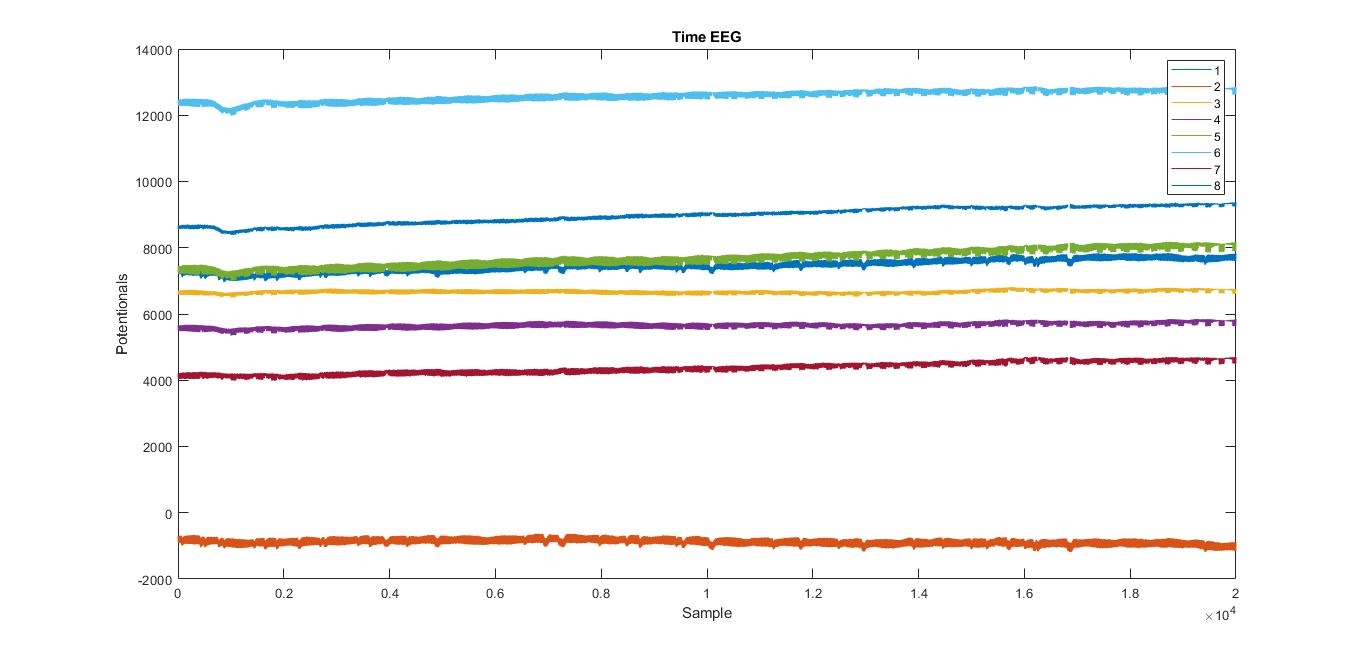
I posted above the raw data graphs. I’m going to apply filters with the next step (including bandpass). 10 days before recording these data, I had a good assistant: she was treated with electrode gel in a quality manner. The raw data graph of that record is shown below. There was also a neutral state, but then did not recognize what resistance was in the channels. Thank you for the indicated links, I came to the conclusion that 30 kOhm permutation is permissible, and 5000 kOhm must be overcome. But some channels (sometimes 1) show a negative uVRMS. Could this be or is it a mistake?
Best regards
Did you see my earlier comment:
You must remove the DC offset with a DSP filter. Otherwise the graph makes no sense. And also, fuzzy looking lines usually imply significant mains noise.