
sources of crosstalk and interference in EOG signals [resolved]

I'm trying to build a user-friendly EOG band to detect eye saccades. I'd like to use a cable sleeve and the 3d printed enclosure (see picture). However, I see this is adding a lot of noise. Any suggestions how to mitigate these problems but still have a user-friendly device?
These are the tests I did:
2. No sleeve, no enclosure. Battery next to the board -> No interference
3. No sleeve, board inside the enclosure. Battery inside enclosure-> high-frequency noise, EOG still useful.
4. No sleeve, board inside the enclosure. Battery outside -> high-frequency noise showing depending on the position. I'm not sure if the problem is the battery or the cables.
5. Cables inside sleeve. No enclosure -> Lot of noise, EOG impossible to recover. 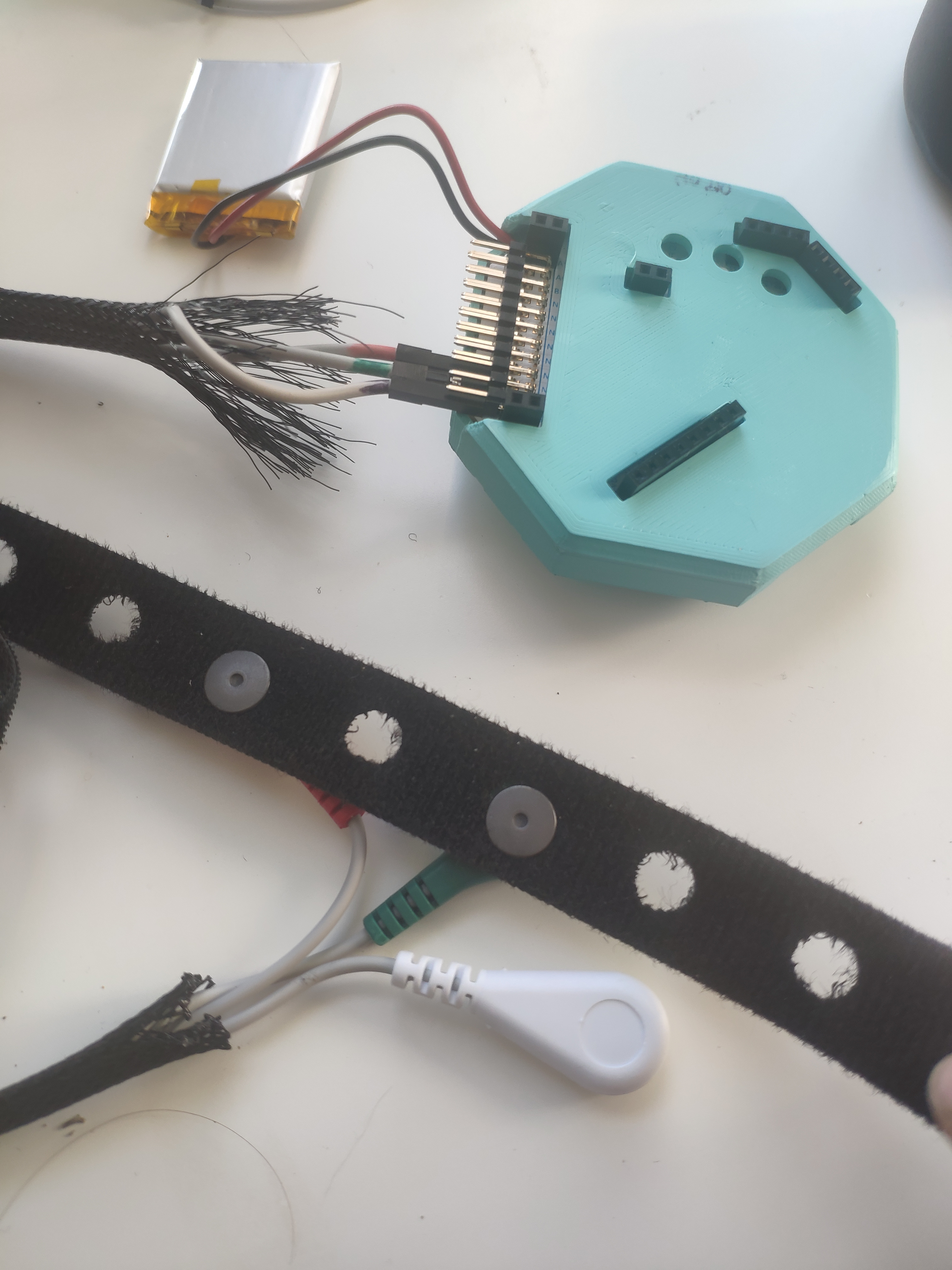
Comments
Hi Skiria,
EOG is normally measured similarly to EMG, with bipolar placements: left and right, and above, below the eyes. Examples are online.
https://www.google.com/search?q=eog+electrode+placement
Your photo seems to show placements on a 'band' around the head, which is not the typical EOG positioning. Also, most EOG uses stick on small pre-gelled adhesive snap electrodes, for highest signal quality. Dry electrodes will likely perform less well. Because the skin impedance of such dry passive electrodes is much much higher than the adhesive EMG / ECG electrodes, this will also tend to couple into higher levels of environmental noise.
re: battery positioning and noise / interference. The battery is a DC source, so should not be inducing any noise regardless of positioning.
re: cable sleeve, bundling cables.
It is possible that bundling cables in close proximity will increase the electrical coupling that happens via capacitive and inductive fields. I think if you follow recommended EOG placements, your noise situation will be under control and even bundled wires will not be much of an issue.
Regards, William
This appears to be the headband you are using, but the placement of the forehead dry flat electrodes will not give optimal EOG data, because they are not positioned EMG-style in bipolar (two wires per channel) locations. EOG is in essence EMG for eye muscles.
https://shop.openbci.com/products/openbci-eeg-headband-kit
To kind of mimic what the recommended EOG positions are, you could move your left / right pair farther outward, and wire the same as a bipolar EMG setup. It still will be (likely much) less signal quality that the recommended EOG locations. And additionally, you are only getting left / right movements, not up down.
Also note that your photo has the electrodes wired up as "EEG style", with the SRB2 reference, and two separate channels, channel 1 and 2. Instead you want to measure voltage between the red and green wires on the plus minus pins of the SAME channel. And move the red / green as far apart as you can. Then attach the white electrode to the center of the forehead, and it is wired to BIAS, NOT SRB2. BIAS is the same as Ground, and all biosignals need a ground wire.
I forgot to mention that. I'm actually using 3 electrodes as in this configuration https://www.mdpi.com/1424-8220/17/7/1485 for simplicity. Hence, SRB2 is my common reference for vertical and horizontal. I wasn't using the BIAS. This configuration works with no sleeve, no enclosure (see last pict)
It's unclear to me what the ground/bias does. When I add it, it adds a lot of noise. Could you clarify why I should use bias and where should I place it?
Signal with bias on forehead (lowpass at 10Hz)

Signal without bias (lowpass at 10Hz)
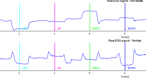
Figure 1a in the paper is the same as normal EOG placement. Figure 1b, the new layout, still has the horizontal electrodes (over the eyes), much farther apart than your headband shows. The farther the spacing, the larger should be the signal, would be my guess, which is why traditional EOG places them to the left of the left eye, and to the right of the right eye.
All EMG / EOG placements are differential. Your wiring shows a common reference, and the white (SRB2) wire is not shown as far as where it goes.
All signal processing on the Cyton should include either a bandpass (say .5 Hz to whatever high freq you want, you mention 10Hz), or a highpass at .5 Hz to remove any DC offset from the DC coupled amplifier used in the Cyton ADS1299.
Bias / ground is recommended for all biosignal applications. It has two functions: centers the differential amplifiers; and also injects a slight anti-mains signal to attempt to cancel some of the mains noise.
SRB2 "reference electrode" is generally NOT used in EMG, ECG, EOG applications. As they are measured differentially on each channel via the plus and minus pins on each channel. Where do you place your 'vertical' electrode? It looks like from the paper, the 'common' electrode is directly over the right eye. Then first channel is over the left eye, and second channel above the lower right eye electrode. Not sure how your headband is doing this, are you using a stick on electrode for second channel? If you are using the 'common' electrode setup as in the figure 1b diagram, then I suppose you could wire it to SRB2, but your original photo does not show this.
Your recent graphs show what appears to be mains / environmental noise / high frequency noise in the first graph. Are you using a notch filter at the mains frequency, as well as the highpass at .5 Hz?
See also the discussion in the paper in section 3.1 on "baseline drift" in this forehead EOG technique. They had to specifically eliminate it with signal processing. The .5 Hz highpass will help, but you will need to do more.
The paper states that the electrodes used were Ag/AgCl, but did not state if they were wet or dry. My guess is that they were wet, because other portions of the paper state that the unusual EOG position used here resulted in signals many times lower amplitude than conventional EOG (3 or 8 times weaker).
Your highpass or low edge of bandpass may need to be lower than .5 Hz. Because basically EOG is recording a DC potential shift. The lower you place the edge, the more "DC-like" characteristics are admitted. So you might want to experiment where to place the edge, such that you remove most of the "DC offset" inherent to a DC coupled amplifier (the ADS1299 in Cyton). But still preserve enough of the EOG "level-like" quality. This may also address some of the "baseline drift" concerns in the paper.
So values to try might be: .5, .4, .3, .2, .1, etc. Or even fine tuning with one of these and the hundredths position.
I'm only using 3 electrodes (like configuration 1b). Hence, the electrode connected in SRB2 is the differential for both vertical (ch1) and horizontal (ch2) channels. My understanding of the OpenBCI board is that I'd get the same differential signal if I connect Ch1+ and Ch1-, than Ch1 and SRB. Is that correct?
Drift is not a problem, my algorithm removes it. I can detect most of the eye saccades with the same configuration 1b of the paper (but without ground). However, I can't explain the high frequency that I see with the ground electrode (in the pictures, it's filtered at 10Hz but its a very high frequency noise that only happens when I add ground). Any idea?
I'll test it with sticky electrodes to see if I still get crosstalk and other interference. But I'd really like to have the device more user friendly with only 3 dry electrodes (or 3 + ground) and cables in some sort of sleeve.
Yes, I did say in comments above that you could use SRB2 as common reference. But I do not see a correspondence with figure 1b and your headband placements. Nor do I see that SRB2 is connected to the electrode above the right eye. Why are your two flat electrodes so close together, etc.?
Did you see my previous comment about using a notch filter at your mains frequency? This is always advised. The figure 1b also uses a Ground. As does almost all EEG, ECG, EMG, EOG. With the changes mentioned in these comments, your anomalous signal behavior results may be eliminated. For example, battery position should make no difference in noise levels. But if your configuration is picking up environmental noise from nearby power cables, wall/floor conduits, extension cords, wall warts / power supplies, LED / CFL lights, conductive concrete floors, etc. etc., environmental noise is ubiquitous.
Contact the paper authors and see what Ag/AgCl electrodes they actually used. My guess is that they had gel or some sort of wet contact. The paper mentions in several places that these modified EOG placements have very much weaker signals than standard EOG. As the signal to noise ratio decreases, and skin impedance increases, environmental noise becomes harder to deal with.
See this page for an example of a DIY headband system that uses either water or saline dampened pads with flat Ag/AgCl electrodes, to produce signal quality equal to wet Ag/AgCl systems.
https://sites.google.com/site/biofeedbackpages/velcro-saline-sensors?authuser=0
The same site also lists other saline / water based headsets.
https://sites.google.com/site/biofeedbackpages/velcro-saline-sensors/commercial-saline-sensors?authuser=0
Regards, William
By your description, your enclosure is acting as an antenna and picking up artifacts from the environment. You might try temporarily connecting the enclosure to one of your grounds or bias pins -- this may either make things much worse or might eliminate the artifact, depending on how the coupling works out phase-wise.
As for the sleeve making things worse, most cabling for EEG signals has a very thin conductive wrapping (a common conductive layer) against the wires under the plastic or rubber sheathing. You could try wrapping a conductive material around the wires before putting the sheath on them.
Ground placed on the foreground doesn't seem to help at all (as I shared in prev post). However, if I place it on the earlobe, the EOG I get with sleeve + enclosure has interference but with signal processing could be useful. Most papers place EOG on foreground but I did see a couple that place it on the earlobe. Ground location doesn't really matter, correct?
Have you implemented the notch filter at your mains frequency, as mentioned previously? Ground (Bias) location does not matter really. But the fact that you see a difference between ear lobe and forehead is odd and unexpected. Might point to electromagnetic field interference in your area. Did you see previous comment regarding power supplies, extension cords, conduits, etc.??
I keep harping on the poor skin impedance of the flat electrodes. Use the GUI to check actual impedance values (new Widget). With the headband you are using, skin impedance will be very dependent upon how tight the headband is fastened.
I tested it in a different location and it worked fine. Seems like the problem was magnetic interference in the area.