
Add daisy module to ADS1299EEGFE-pdk
 Gualor
Milan
Gualor
Milan
Hi everyone!
I'm a student of biomedical engineering currently working on a master thesis project regarding online EEG data processing . What I am about to ask is a bit unusual and part of a backup plan, since the company I'm partnering with for this project commissioned me to find a low cost solution only using the Daisy Module of the Cyton board, which I later discovered didn't have any data ready pin and internal clock settings (since it is intended to be use with the Cyton board only of course).
Fortunately I already had an evaluation board from Texas Instrument called ADS1299EEGFE-pdk, which both provides a DRDY signal and the option to output its clock signal.
Given this long premise, my final setup will (hopefully) be the following:
1) Gapuino board, which is my main microcontroller able to perform really fast processing on incoming data. With Gapuino I'm already able to set registers of ADS1299EEGFE and read data correctly via SPI.
2) ADS1299EEGFE-pdk connected to the SPI bus and DRDY signal going into an interrupt pin on the Gapuino.
3) Daisy module connected to the SPI bus with its own Chip Select pin, receiving an external clock from the ADS1299EEGFE in cascade mode configuration.
I checked the schematics of Cyton and Daisy module multiple times to understand the functioning and replicate the same thing but with the use of the evaluation board and a microcontroller, but I couldn't make it work (even though I don't find any reasons why it shouldn't have) and kept reading zeros from the registers.
To avoid overlap multiple problems, I am testing only the daisy module with the external clock of the evaluation board (which only provides its clock but is not connected to SPI bus), its /CS pin always tied low and its /RESET pin always tied high, in order to just read the ID register (not trying to read data yet, so no need for DRDY for now).
The logic analyzer confirmed that Gapuino is sending everything correct and the external clock of 2.048 Hz is provided:
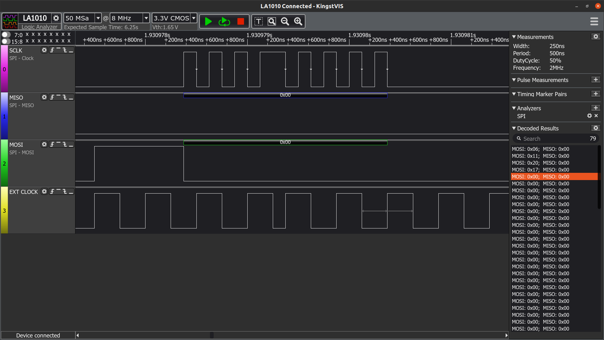
SPI is at 4MHz frequency, and the following sequence is sent in order to read registers (all time delays after sending each opcode is set as specified in the datasheet):
0x06 -> RESET command
0x11 -> SDATAC command
0x20 -> READ command
0x17 -> READ 24 registers argument
0x00 -> dummy bytes (sent 24 times)
I will also provide you with the pin header connections for the daisy module, which is the following:
DVDD    -> 3.3 volt (outputted by Gapuino)
GND     -> GND (Gapuino)
MISO    -> MISO (Gapuino)
SCK     -> SCLK (Gapuino)
RST     -> 3.3 volt (Gapuino)
CLK     -> external clock (ADS1299EEGFE-pdk)
MOSI    -> MOSI (Gapuino)
CS2     -> GND (Gapuino)
Thanks in advance to anyone who is kind enough to help me understand what I'm missing here.
Best regards,
Lorenzo