
Huge offset. Possible causes?

Hi!
We are working on a design that requires the signal to be not highpassed (include all the information down to DC). However, the signal i am getting is largely offset. Here are the pics:
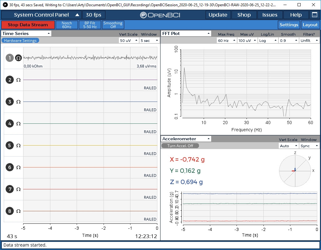

I am using Ag/AgCl electrodes with gel and a cap. Those are barely used, not mixed by type and the skin is thoroughly prepped before. As you may see in the OpenBCI screenshot, the impedance achieved is very low. It is a bipolar montage, T4/Fp2 with the ground on right ear. A screen of a simple BioEra design shows the offset.
I also have cupped electrodes which need to be used with Ten20 paste. The paste is on the back order and i will receive it by the middle of the next week. Any reason to blame the electrodes?
Comments
Arty, hi.
The DC offset you see is completely expected and is the case with all types of electrodes.
https://openbci.com/forum/index.php?p=/discussion/201/large-millivolt-data-values-fbeeg-full-band-eeg
You can definitely include ILF/ISF (infra low frequency / infra slow fluctuations) in your work, as did some of the research cited in that thread. However I'm not clear on the source of your RAILED condition on channels 2 through 8. I assume these are floating channels and you did not turn them off. Typically the ILF is either filtered OUT, or filtered separately from normal EEG range (say .5 Hz to 45 Hz.)
I see from your past threads that you are working on a BioEra ILF design. So I'm not quite sure what is unexpected about what you are seeing. Typical ILF designs do a long term average on the DC portion (controlled by a filter), then give feedback based on how the shorter term DC values move up or down relative to that long term baseline.
Regards, William
William,
Thanks for the link!
I tried turning the rest of the channels off. As you can see in the screenshot, the icons of the channels 2-8 are dark, this happened after i clicked on each channel icon. Not sure why it still read 'RAILED'. I only used 1st channel. What do you think about 0kOhm reading in the screenshot?
As for the design - yes, it is an attempt of creating an ILF design. Actually, i wasn't sure how Othmers did it. In this particular design the feedback is given to the signal amplitude. I thought that comparing the signal to a long average is more of ISF territory.
I would be suspect of the 0K impedance number. Might indicate something miss-wired. You cannot get impedance that low from skin. The fact the other channels show RAILED is also odd. Are you using the latest GUI v 5?
Yes, the GUI is the last available on the site.
I am using BIAS, SRB and N1P pins. Those are connected to electrodes which are placed at ear, Fp2 and T4. I also tried the same montage with saline electrodes - offset was about twice bigger.
What RAILED means, anyway?
https://www.google.com/search?as_q=railed&as_sitesearch=openbci.com
Using button at upper right column. If the channels are floating RAILED can easily happen. Only use channel / SRB / Bias pins CLOSEST to board. Actual pin names for those are IN1N, IN2N, ... IN8N. And SRB2, Bias. Farthest pins are IN1P through IN8P. And SRB1.
Sure, i am using only closer to board pins.
Will skim through the "Railed" threads, William.
BTW, i am using the V3-32 version of the board which i got from kickstarter. Any reason to go through firmware update? Never updated it.
"V3-32" is just the PC board version. Not the firmware version. The bogus readouts from the GUI now make more sense. I'm surprised your board works with the GUI at all.
BioEra uses the original serial port protocol, so is not impacted (generally) by firmware serial protocol version. However GUI IS impacted, which is why your GUI screen is bogus. Upgrade instructions are here:
https://docs.openbci.com/docs/02Cyton/CytonProgram
https://github.com/OpenBCI/OpenBCI_Cyton_Library/blob/master/UPGRADE_GUIDE.md
Railed means the wire has a very large DC offset, one too large to allow it to be shown on the graph given its units. See:
https://dsp.stackexchange.com/questions/58672/what-does-the-term-railed-mean-in-signal-processing
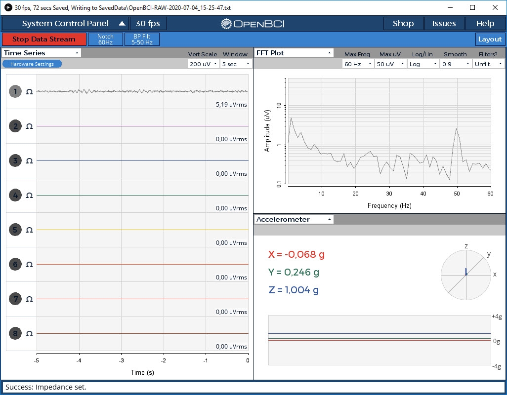
Ok, i decided to try an older version of GUI (3.3.2 i believe) before upgrading the firmware. Seems to work fine. William, if one's goal is training with BioEra, are there reasons to upgrade?
As seen on the screenshots, there are no RAILED channels and impedance measure looks decent. Aside from a 50Hz artifact, the rest looks col to me. It is T3/T4 bipolar montage with a ground at Fp2.

The screenshot below shows a low passed signal at 0.02Hz with 4th order Butterworth filter (blue) and a 30s long average of the same signal (red). Does it look ok? Or should i be concerned with the quality of the signal or maybe the connection? Same T3/T4 bipolar montage.
If you will only use BioEra, then yes, you can continue to use (very) old Cyton / RFduino firmware. Note however that the old firmware has various bugs, such as the stream sometimes freezing, etc. These were fixed in later revisions.
And also with the GUI, the one you are using is YEARS behind the improvements and fixes in GUI v5.
re: ILF neurofeedback. As you are aware, all of these protocols are considered proprietary and as yet I know of no publicly available BioEra designs that are proven to work reliably. I'm not releasing the one I developed, because I don't want to ruffle the feathers of the technology inventors (Othmer's and Mark Smith). Besides, each implementation has subtle differences. Smith is definitely a different animal than Othmer, than mine. Compujohny says that his has similar effects to Othmer, but again no one is sharing code / protocols.
You just have to fiddle with the feedback until it is tracking and feeding back, the gentle up and down movement of the infraslow wave.
Regards, William
I understand that the ISF/ILF stuff is proprietary and asking how to make such design is kinda silly. I was more concerned with the signal and how it looks, e.g. whether such amplitude, the swings, etc are expected at this frequency range since i don't have experience at this and there are not many who does .
.
Anyway, thank you a lot! Your answers were really helpful.