
How can I go into debug mode?

Hello! My goal right now is to use the DEBUG board mode for the OpenBCI Cyton+Daisy for troubleshoot some of the problems with a new firmware I am trying to work at. ! 
From the instructions from this part of the code. However, it seems like I am not able to find the Board_Defs.h in my Windows computer. 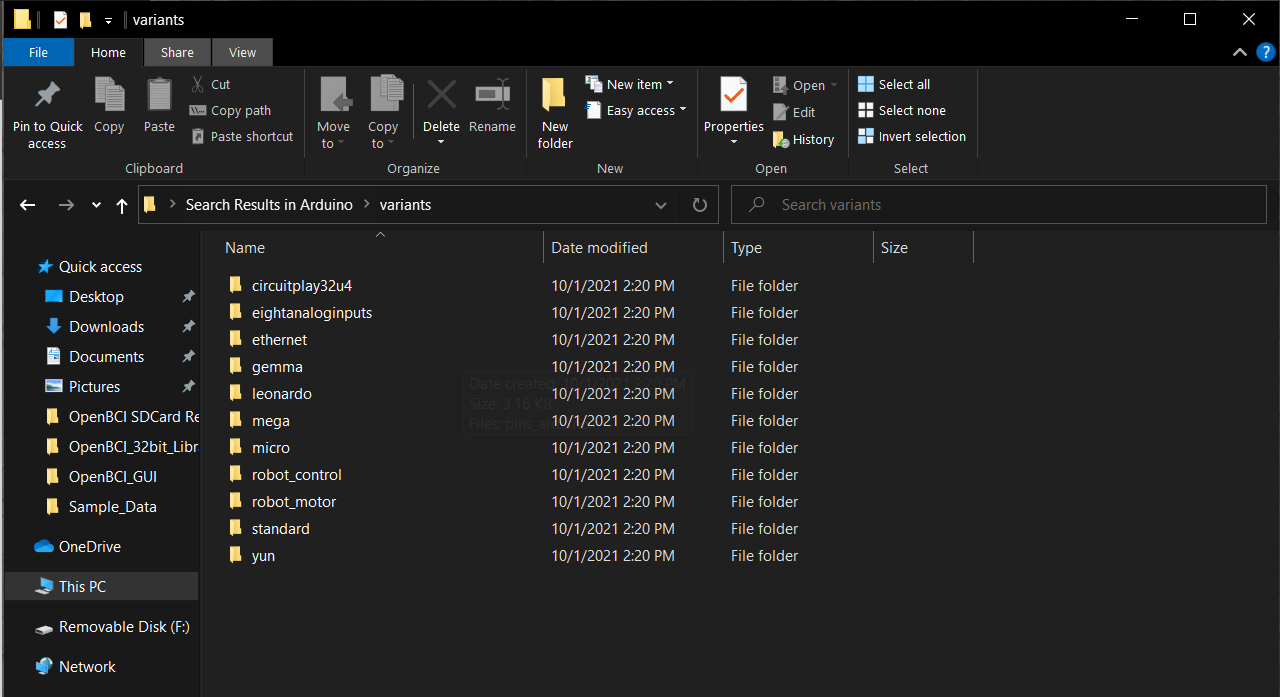
Attached is the picture of the file. Apparently my variants file is in Programs File x86. Nevertheless, I am still not able to find the Board_Defs.h. Please help!
Comments
MSL, hi.
My hunch is that you are looking at an old section of code or comments that was not updated with the v3 firmware. In the v3 firmware, you can turn on the extra PIC32 serial port (for debugging), with an SDK 'board mode' command. Thus no code mods should be needed.
https://docs.openbci.com/Cyton/CytonSDK/#board-mode
So the command string sent over the Cyton main Cyton serial port would be: "/1".
Related firmware source code:
https://github.com/OpenBCI/OpenBCI_Cyton_Library/search?q=board_mode_debug
https://github.com/OpenBCI/OpenBCI_Cyton_Library/search?q=curdebugmode
Regards, William
I worked on the debug mode. Even though I've sent the "/1" command, I am not seeing anything in the serial monitor that is comprehendible.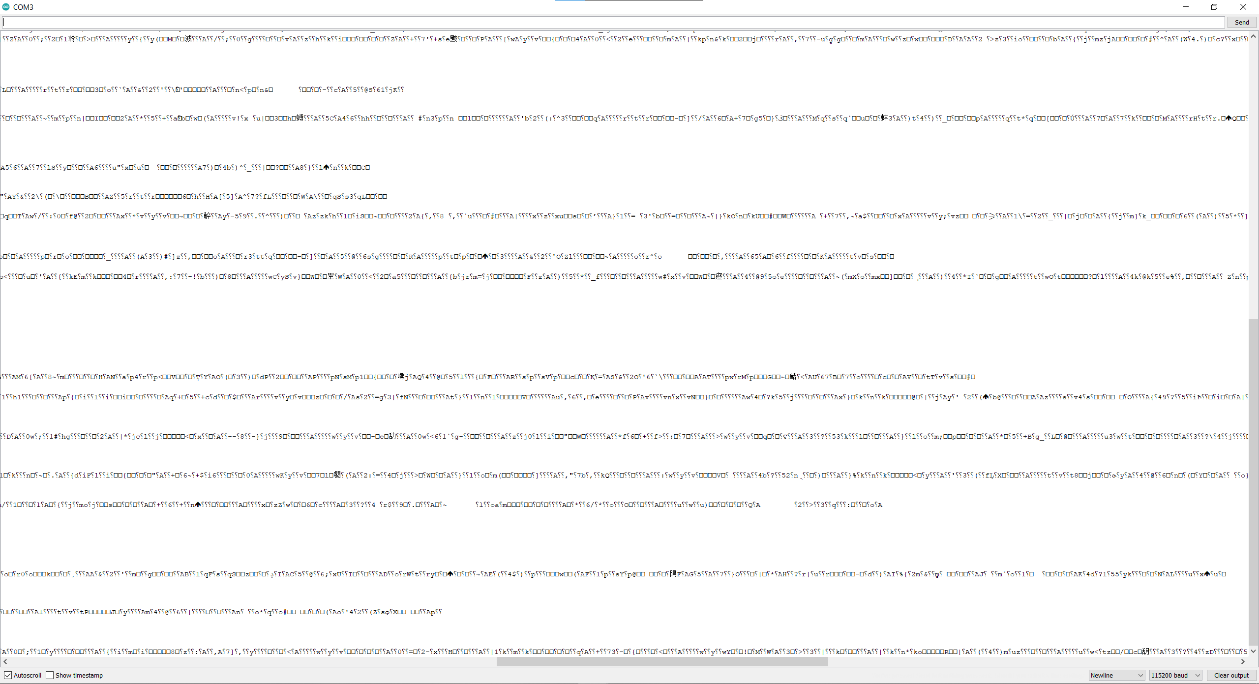 The picture is of the serial monitor from arduino. The FTDI is connected to the Rx and the Tx of the WeDAQ with the ground connection to WeDAQ ground. After reviewing the code comment, it says to probe the
  pin 10 and 12 for SER1_TX_PIN and SER1_RX_PIN. I did not change the code mods as @wjcroft suggested but still try to probe the pin 10 and 12 which is PGD and PGC of the PIC32. However, I still get the incomprehensible symbols from the serial monitor. Is there a best way to resolve this?
Very Respectfully,
Min
Check the source code. Are you sure you have the correct baud rate selected? What are you trying to output via the debug port?
Hello. I have the baud rate set to 115200 as stated on the code and have a common ground for the FTDI and the board. We noticed in the code that the debug mode have various serial comments when there are changes made or errors in the board. We hope to utilize the debug mode function in order to debug our firmware code that we've made.
Is it possible that your usb serial port adapter, is expecting 0 to 5V TTL signals vs 0 to 3.3V signals? Or even weirder, if it is expecting RS232 signal levels? You can find usb serial adapters that accept 3.3V logic.
https://en.wikipedia.org/wiki/RS-232#Voltage_levels
We have the FTDI Beefy 3 which uses 3.3V.
https://www.amazon.com/SparkFun-Beefy-FTDI-Basic-Breakout/dp/B01C4W7NVK
Your October 29 terminal simulator screen shot, seems to show random garbage characters. Are you sure you have the FTDI receive pin / ground, wired correctly? Any pattern you see on the garbage, does it start, stop, etc., when doing certain Cyton operations? Have you tested this receive capability with another serial port output hookup? To verify the board and your wiring are correct?
Hello @wjcroft. Thanks for helping with this. I have check multiple times for the FTDI setup. I was able to program the board successfully with the same setup so I am sure it is wired correctly. I don't see and noticeable patterns in the garbage characters. I do see some changes when I write to SD card, but only in as garbage characters and not anything else that seems understandable. Hmmmm any suggestions on what I can try?