I have built a BCI system with a self-3D printed headset, FRI Ag-AgCl dry electrodes and a Cyton board, based on OpenBCI online tutorials and models. My high school daughter is using the system in a project to detect SMRs in people with locked-in-syndrome. Dry spiked electrodes were preferred to avoid using gel with wet electrodes.
I was very interested in trying to find and use active electrodes with the OpenBCI, but did not believe the Olimex flat surface electrodes (https://www.olimex.com/Products/EEG/Electrodes/EEG-AE/open-source-hardware) would ensure good skin contact through hair. After receiving a $3,000 quote for a set of 8 g.Sahara electrodes from g.tec, I decided to try to build them myself. The following work is based on the excellent ideas, instructions and schematics described in the active electrode pages at the OpenEEG project (http://openeeg.sourceforge.net/doc/hw/ae.html), especially from Jarek Foltynski, Jim Peters and Pedro Ortega. The electrical diagram is the circuit suggested by Joerg Hansmann which is a modified version of the V2 active electrodes by Jarek Foltynski (you can find all the schematics in the link above).
I tried to achieve various goals with these electrodes: use the Ag-AgCl FRI dry electrodes, have the smallest footprint possible, be able to use the electrodes with the Cyton board and keep the costs to a minimum. The solution of the first problem was to connect the FRI electrodes to the PCB with a copper rivet cut to size and soldered to the PCB. The electronic components were arranged to fit in a 3/4” x 3/4” (19 X 19 mm) size PCB (7 X 7 holes). The height of the PCB with soldered components is just a bit more than 1/4” (6.5 mm). A shielded 3-wire cable was used to connect the electrodes to the Cyton board: the 5V positive and negative wires were connected to AVDD and AVSS outputs and the signal wire to the Cyton channels. The cable shield was connected to the GND pin; not sure if it helps, but it doesn’t hurt either. In order to be able to connect all 8 channels, I built a multiple pins connector block to plug into the AVDD and AVSS outputs. A third row of pins was added to the connector block for the GND connections. The total cost of each active electrode was a little less than $5 (including shipping): $1.5 for the dry electrodes from FRI, $2.5 for the electronic components from Mouser Electronics and less than $1 for the PCBs, cable, copper rivets and pins from Amazon. I also added a 3D printed enclosure: it protects the electronics, puts pressure on the spiked electrode improving the contact with the copper rivet, and it looks better. The enclosure can also be lined internally with a copper plate that act as shielding to the electrode circuit; the shielding can be connected to the PCB according to the diagram. Next goal will be to find the best way to attach the electrodes to the Ultracortex headset: they have a small footprint, but not small enough to fit them on the spring-loaded cylinders of the headset.
Below are some images of the assembled electrodes, connector and some screenshots of OpenBCI GUI comparing a regular passive dry electrodes with the active ones (passive – channel 1, active – channel 2, both placed on the forehead).
Top and bottom view of the electrode


Electrode with 3D printed enclosure

Cyton board connector block


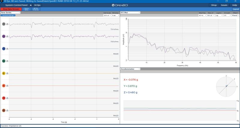
Eye blinks (channel 1 – passive, channel 2 – active)
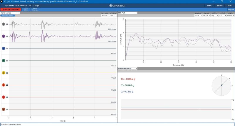
Teeth grinding (channel 1 – passive, channel 2 – active)
Impedance (channel 1 – passive, channel 2 – active)

Do you have a schematic and part number for the copper rivet you used? I’m working on a few different active electrodes and want to use differential signaling. I was thinking of using a SAS(serial attached sata) cable to connect multiple differential electrodes.
Sorry for the late reply, just saw your post. Here is the Amazon link for the rivets: https://www.amazon.com/gp/product/B01IZ01GW2/ref=oh_aui_search_detailpage?ie=UTF8&psc=1
I ran the rivet through the electrode and PCB holes, pushed it to ensure good contact, cut it on the other side, and soldered it immediately. Later it starts moving again, but the 3D printed enclosure pushed the electrode down and ensures good contact between rivet and electrodes.
Not sure about using the SAS cable, but I strongly recommend the use of a shielded cable to reduce the noise. Please note that the electrodes I built are not amplified, the gain is 1.
Hey, I’m interested in the way you set up those regarding the hardware menu settings?
Could you explain?
Also how did you put a passive and an active electrode at the same time?
Is your active channel made of two electrodes or only one?
Looking forward to hearing your answers.
I am not sure what you mean with hardware menu settings; the active electrodes supply the same signal to the board as the passive ones, but the circuit makes sure that the impedance is drastically reduced. It is also possible to increase the gain at the electrode to amplify the signal, but this specific circuit has a gain=1.
I built a connector block (see photo) that plugs into the AVDD and AVSS pins on the board. These supply +2.5V and -2.5V needed to power the active electrode circuit. There are two rows of 8 pins each on the connector block; one is connected to AVDD and the other to AVSS. Up to 8 active electrodes can be plugged into this connector block and be powered by the board itself. I added another row with 9 pins and connected one of them with the ground (AGND pin). All shields were plugged into these pins to try to reduce the noise.
The signal wires were plugged into the 8 channel pins, just like the passive electrodes. So, you can have both passive and active electrodes connected to the board; the only difference is that the active electrodes will have 3 more wires conected to it: positive to +2.5V, negative to -2.5V and shield to the ground. Hope I answered your question.